12
ENGLISH
2017 XX XX
Year of Manufacture
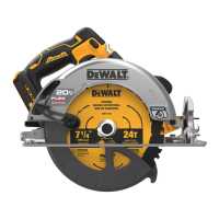
Description (Fig. A)
WARNING: Never modify the power tool or any part of it.
Damage or personal injury couldresult.
1
Trigger switch lock-off button
2
Trigger switch
3
Battery pack
4
Depth adjustment lever (Fig.E)
5
Base plate
6
Lower blade guard retracting lever
7
Lower blade guard
8
Blade clamping screw
9
Kerf indicator
10
Bevel adjustment lever
11
Blade lock button
12
Auxiliary handle
13
Battery release button
14
Blade wrench (Fig.E)
15
Worklight
16
Rafer Hook
Intended Use
These heavy-duty circular saws are designed for professional
wood cutting applications. Do not cut metal, plastic, concrete,
masonry or fiber cement materials. DO NOT use water feed
attachments with this saw. DO NOT use abrasive wheels or
blades. DO NOT use under wet co0nditions or in the presence
of flammable liquids orgases.
These heavy-duty saws are professional powertools.
DO NOT let children come into contact with the tool.
Supervision is required when inexperienced operators use
thistool.
• Young children and the infirm. This appliance is not
intended for use by young children or infirm persons
withoutsupervision.
• This product is not intended for use by persons (including
children) suffering from diminished physical, sensory or
mental abilities; lack of experience, knowledge or skills
unless they are supervised by a person responsible for their
safety. Children should never be left alone with thisproduct.
ASSEMBLY AND ADJUSTMENTS
WARNING: To reduce the risk of serious personal
injury, turn tool off and disconnect battery pack
before making any adjustments or removing/
installing attachments or accessories. An accidental
start-up can causeinjury.
WARNING: Use only DeWALT battery packs andchargers.
Inserting and Removing the Battery Pack
from the Tool (Fig. A)
NOTE: Make sure your battery pack
3
is fullycharged.
To Install the Battery Pack into the Tool
Handle
1. Align the battery pack
3
with the rails inside the tool’s
handle (Fig. A).
2. Slide it into the handle until the battery pack is firmly seated
in the tool and ensure that you hear the lock snap intoplace.
To Remove the Battery Pack from the Tool
1. Press the release button
13
and firmly pull the battery pack
out of the toolhandle.
2. Insert battery pack into the charger as described in the
charger section of thismanual.
Fuel Gauge Battery Packs (Fig. A)
Some DeWALT battery packs include a fuel gauge which
consists of three green LED lights that indicate the level of
charge remaining in the batterypack.
To actuate the fuel gauge, press and hold the fuel gauge button
32
. A combination of the three green LED lights will illuminate
designating the level of charge left. When the level of charge
in the battery is below the usable limit, the fuel gauge will not
illuminate and the battery will need to berecharged.
NOTE: The fuel gauge is only an indication of the charge left on
the battery pack. It does not indicate tool functionality and is
subject to variation based on product components, temperature
and end-userapplication.
Changing Blades
To Install the Blade (Fig.C–E)
1. Remove thebattery.
2. Using the lower guard lever
6
, retract the lower blade
guard
7
and place blade on saw spindle against the inner
clamp washer
17
, making sure that the blade will rotate
in the proper direction (the direction of the rotation arrow
on the saw blade and the teeth must point in the same
direction as the direction of rotation arrow on the saw). Do
not assume that the printing on the blade will always be
facing you when properly installed. When retracting the
lower blade guard to install the blade, check the condition
and operation of the lower blade guard to assure that it is
working properly. Make sure it moves freely and does not
touch the blade or any other part, in all angles and depths
ofcut.
3. Place outer clamp washer
16
on saw spindle with the
beveled edge facing out. Make sure the 30 mm diameter on
the blade side of the clamp fits into the 30 mm hole in the
saw blade to ensure centering of theblade.
4. Thread the blade clamping screw
8
onto the saw spindle
by hand (screw has right-hand threads and must be turned
clockwise to tighten).
5. Depress the blade lock
11
while turning the saw spindle
with the blade wrench
14
stored underneath the battery
compartment, until the blade lock engages and the blade
stopsrotating.
6. Tighten the blade clamping screw firmly with the
bladewrench.

 Loading...