ENGLISH
10
Worklight (Fig. A)
CAUTION: Do not stare into worklight. Serious eye
injury couldresult.
There is a worklight
15
located just below the blade lock
button
11
. The worklight is activated when the trigger
switch is depressed, and will automatically turn off 20
seconds after the trigger switch is released. If the trigger
switch remains depressed, the worklight will remainon.
NOTE: The worklight is for lighting the immediate work
surface and is not intended to be used as aflashlight.
Trigger Switch (Fig. G)
WARNING: This tool has no provision to lock the
trigger switch in the ON position and should never be
locked ON by any othermeans.
Release the trigger switch lock-off button
1
by pressing
the button as shown. Pull the trigger switch
2
to turn the
motor on. Releasing the trigger switch turns the motoroff.
Fig. G
1
2
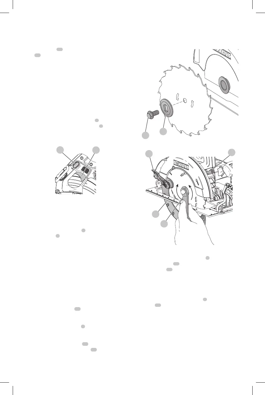
Changing Blades (Fig. H, I)
WARNING: Remove battery from tool before
changingblades.
To install the Blade (Fig. H, I)
1. Retract the lower blade guard
7
using the lower blade
retracting lever
6
and place the blade on the saw
spindle against the inner clamp washer, making sure
that the blade will rotate in the proper direction (the
direction of the rotation arrow on the saw blade and the
teeth must point in the same direction as the direction
of rotation arrow on the lower blade guard). Do not
assume that the printing on the blade will always be
facing you when properly installed. When retracting
the lower blade guard to install the blade, check the
condition and operation of the lower blade guard to
assure that it is working properly. Make sure it moves
freely and does not touch the blade or any other part, in
all angles and depths ofcut.
2. Place outer clamp washer
17
on saw spindle with the
large flat surface against the blade with beveled side
facingout.
3. Thread blade clamping screw
8
into saw spindle by
hand (screw has right-hand threads and must be turned
clockwise to tighten).
4. Depress the blade lock button
11
while turning the
saw spindle with the blade wrench
14
until the blade
lock engages and the blade stops rotating (Fig.I).
5. Tighten the blade clamping screw firmly with the
bladewrench.
NOTE: Never engage the blade lock while saw is running,
or engage in an effort to stop the tool. Never turn the saw
on while the blade lock is engaged. Serious damage to your
saw willresult.
Fig. H
8
17
Fig. I
LOOSEN
(counterclockwise)
7
14
11
TIGHTEN
(clockwise)
6
To Replace the Blade (Fig. H, I)
1. To loosen the blade clamping screw
8
, depress the
blade lock button
11
and turn the saw spindle with the
blade wrench
14
until the blade lock engages and the
blade stops rotating. With the blade lock engaged, turn
the blade clamping screw counterclockwise with the
blade wrench (screw has right-hand threads and must
be turned counterclockwise to loosen).
2. Remove the blade clamping screw
8
and outer clamp
washer
17
only. Remove oldblade.
3. Clean any sawdust that may have accumulated in the
guard or clamp washer area and check the condition
and operation of the lower blade guard as previously
outlined. Do not lubricate thisarea.
4. Select the proper blade for the application (see Blades).
Always use blades that are the correct size (diameter)
with the proper size and shape center hole for mounting
on the saw spindle. Always assure that the maximum
recommended speed (rpm) on the saw blade meets or
exceeds the speed (rpm) of thesaw.

 Loading...