11
ENGLISH
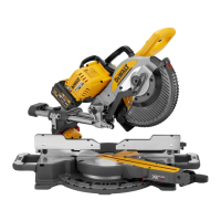
This unit is designed for use with a nominal blade diameter 250mm carbide
tipblade.
DO NOT use under wet conditions or in presence of flammable liquids
orgases.
These miter saws are professional powertools.
DO NOT let children come into contact with the tool. Supervision is
required when inexperienced operators use thistool.
WARNING! Do not use the machine for purposes other thanintended.
• Young children and the infirm. This appliance is not intended for use
by young children or infirm persons without supervision.
• This product is not intended for use by persons (including children)
suffering from diminished physical, sensory or mental abilities; lack of
experience, knowledge or skills unless they are supervised by a person
responsible for their safety. Children should never be left alone with
thisproduct.
ASSEMBLY
WARNING: To reduce the risk of serious personal injury, turn
machine off and disconnect battery pack before making any
adjustments or removing/installing attachments or accessories.
An accidental start-up can causeinjury.
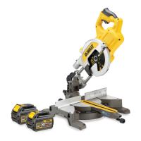
WARNING: Use only
battery packs include a fuel gauge which consists of
three green LED lights that indicate the level of charge remaining in the
batterypack.
To actuate the fuel gauge, press and hold the fuel gauge button
28
. A
combination of the three green LED lights will illuminate designating the
level of charge left. When the level of charge in the battery is below the
usable limit, the fuel gauge will not illuminate and the battery will need to
berecharged.
NOTE: The fuel gauge is only an indication of the charge left on the battery
pack. It does not indicate tool functionality and is subject to variation based
on product components, temperature and end-userapplication.
Bench Mounting (Fig.B, T)
1. Holes
21
are provided in all four feet to facilitate bench mounting.
Bolts with a diameter of 8mm and 80mm in length is suggested.
Always mount your saw firmly to prevent movement. To enhance the
portability, the tool can be mounted to a piece of 12.5mm or thicker
plywood which can then be clamped to your work support or moved to
other job sites andreclamped.
2. When mounting your saw to a piece of plywood, make sure that the
mounting screws do not protrude from the bottom of the wood.
The plywood must sit flush on the work support. When clamping the
saw to any work surface, clamp only on the clamping bosses where
the mounting screw holes are located. Clamping at any other point will
interfere with the proper operation of thesaw.
3. To prevent binding and inaccuracy, be sure the mounting surface is
not warped or otherwise uneven. If the saw rocks on the surface, place
a thin piece of material under one saw foot until the saw is firm on the
mountingsurface.
Mounting the Saw Blade (Fig.A,D, E)
WARNING: To reduce the risk of injury, turn unit off and
disconnect machine from power source before installing and
removing accessories, before adjusting or changing set-ups
or when making repairs. Be sure the trigger switch is in the OFF
position. An accidental start-up can causeinjury.
WARNING: The teeth of a new blade are very sharp and can
bedangerous.
WARNING: Be aware the saw blade shall be replaced in the described
way only. Only use saw blades as specified under Technical Data;
Cat.no.: DT4320 issuggested.
1. Insert the 6mm hex key
25
into the opposite location of the blade
shaft and hold it(Fig.D).
2. Use second hex key as shown in Figure D as spindlelock.
3. Loosen the blade bolt
6
by turning clockwise. Remove the blade bolt
and the outer flange
5
.
4. Press the lower guard lock up release lever
2
to raise the lower blade
guard
7
and remove the saw blade
8
.
5. Install the new saw blade onto the shoulder provided on the inner
flange
32
making sure that the teeth at the bottom edge of the blade
are pointing towards the fence (away from the operator).
6. Replace the outer flange
5
, making sure that the location lugs are
engaged correctly, one on each side of the motorshaft
36
.
7. Tighten the blade bolt
6
by turning anti-clockwise while holding the
6mm hex key
25
engaged with your other hand (Fig.D).
ADJUSTMENTS
WARNING: To reduce the risk of serious personal injury, turn
machine off and disconnect battery pack before making any
adjustments or removing/installing attachments or accessories.
An accidental start-up can causeinjury.
Your mitre saw was accurately adjusted at the factory. If readjustment
due to shipping and handling or any other reason is required, follow the
steps below to adjust your saw. Once made, these adjustments should
remainaccurate.
Adjusting the Traverse Bars for Constant Cutting
Depth (Fig.A,B,F,H)
The blade must run at a constant cutting depth along the full length of the
table and must not touch the fixed table at the rear of the slot or at the front
of the rotating arm. To achieve this, the traverse arms must be perfectly
parallel to the table when the saw head is fullydepressed.
1. Press the lower guard lock up release lever
2
(Fig.A).
2. Press the saw head fully to the rear position and measure the height
from the rotating table
14
to the bottom of the outer flange
5
(Fig.F).
3. Turn the saw head traverse lock
18
(Fig.B).
4. Keeping the saw head fully depressed, pull the head to the end of
itstravel.
5. Measure the height indicated in figureF again. Both values should
beidentical.
6. If adjustment is required, proceed as follows (Fig.H):
a. Loosen the locknut
37
in the bracket
38
and adjust the screw
39
as required, proceeding in smallsteps.
b. Tighten the locknut
37
.
 Loading...