10
ENGLISH
the lower Watt hour rating can exempt the pack from certain shipping
regulations that are imposed upon the higher Watt hour batteries.
For example, the Transport Wh rating
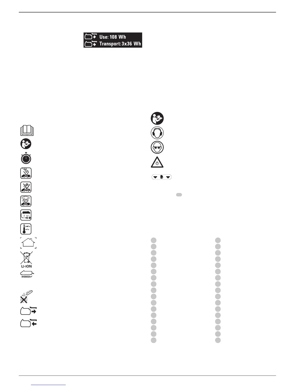
Example of Use and Transport Label Marking
might indicate 3x36 Wh, meaning 3
batteries of 36 Wh each. The Use Wh
rating might indicate 108Wh
(1battery implied).
Storage Recommendations
1. The best storage place is one that is cool and dry away from direct
sunlight and excess heat or cold. For optimum battery performance and
life, store battery packs at room temperature when not inuse.
2. For long storage, it is recommended to store a fully charged battery
pack in a cool, dry place out of the charger for optimalresults.
NOTE: Battery packs should not be stored completely depleted of charge.
The battery pack will need to be recharged beforeuse.
Labels on Charger and Battery Pack
In addition to the pictographs used in this manual, the labels on the charger
and the battery pack may show the following pictographs:
Read instruction manual beforeuse.
See Technical Data for chargingtime.
Do not probe with conductiveobjects.
Do not charge damaged batterypacks.
Do not expose to water.
Have defective cords replacedimmediately.
Charge only between 4 ˚C and 40 ˚C.
Only for indooruse.
Discard the battery pack with due care for theenvironment.
Charge
battery packs only with designated
chargers. Charging battery packs other than the designated
charger may make them burst
or lead to other dangeroussituations.
Do not incinerate the batterypack.
USE (without transport cap). Example: Wh rating indicates 108
Wh (1 battery with 108 Wh).
TRANSPORT (with built-in transport cap). Example: Wh rating
indicates 3 x 36 Wh (3batteries of 36 Wh).
Battery Type
The DCS778 operates on a 54 volt batterypack.
These battery packs may be used: DCB546. Refer to Technical Data for
moreinformation.
Package Contents
The packagecontains:
1 Partly assembled machine
2 hex key (4mm and 6mm)
1 250mm TCT saw blade
1 Material clamp
2 Battery packs (T2 model)
1 Charger (T2 model)
1 Instruction manual
• Check for damage to the tool, parts or accessories which may have
occurred duringtransport.
• Take the time to thoroughly read and understand this manual prior
tooperation.
Markings on Tool
The following pictograms are shown on the tool:
Read instruction manual beforeuse.
Wear earprotection.
Wear eyeprotection.
Visible radiation. Do not stare intolight.
Carrying point
Date Code Position (Fig. B)
The Date Code
57
, which also includes the year of manufacture, is printed
into thehousing.
Example:
2016 XX XX
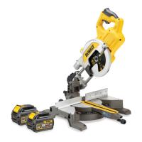
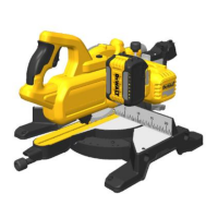
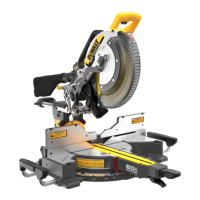
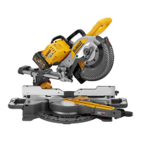
Description (Fig.A–C, E)
WARNING: Never modify the power tool or any part of it. Damage or
personal injury couldresult.
1
Trigger switch
2
Guard lock-up release lever
3
Operating handle
4
Fixed upper guard
5
Outer flange
6
Blade bolt
7
Lower blade guard
8
Saw blade
9
Sliding fence lock knob
10
Fixed table
11
Kerf plate
12
Mitre arm
13
Mitre latch
14
Rotating table/mitre arm
15
Mitre scale
16
Sliding fence
17
Material clamp
18
Traverse lock
19
Bevel clamp handle
20
Bevel scale
21
Bench mounting holes
22
Lock down button
23
Traverse bars
24
Saw head
25
Hex keys
26
Battery pack
27
Battery pack release button
28
Fuel gauge button
29
Lock off switch
30
Override button
31
Carrying handle (left and right)
32
Inner flange (Fig. E)
33
Dust extraction port
34
XPS™ Button
Intended Use
Your
Cordless Compact Mitre Saw has been designed for
professional cutting wood, wood products, aluminum and plastics. It
performs the sawing operations of cross-cutting, bevelling and mitring
easily, accurately andsafely.