9
ENGLISH
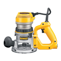
Set‑up: Plunge Base (Fig. A, I, J, K)
Motor Quick Release
1. Open the locking lever
4
on thebase.
2. Grasp the top of the motor unit and lift it from thebase.
Inserting the Motor into the Plunge Base
1. Remove the depth adjustment ring from the motor. It is
not used with the plungebase.
2. Open the locking lever
4
on the base to ensure that the
motor properlyseats.
3. Ensure that the plunge lock lever
17
islocked.
4. Align the flat of the motor’s end cap
27
with pillar
28
and insert the motor into the plunge base until itstops.
5. Close the locking lever
4
.
Operation: Fixed and D–Handle Base
Gripping Locations (Fig. A)
Fixed Handle Base: Grip both knob handles
5
whileoperating.
D-Handle Base: Grip D‑Handle
20
and knob handle
5
whileoperating.
The D‑Handle router base has two positions for the knob to
accommodate right or left handuse.
Trigger Lock (Fig. A)
D-Handle Base Only
To lock the trigger, pull the trigger switch
13
completely,
then push the trigger lock button
14
. The router will remain
on after you remove your finger from the trigger. To unlock
the trigger lock button, pull the trigger and release. The lock
button will pop out and the router will turnoff.
4. Connect the short cord
26
from top of D‑Handle to the
motor as shown. Be sure the cord islocked.
5. Place the toggle switch in the ON position. This allows
the trigger switch on the D‑handle to control therouter.
Adjusting the Depth of Cut (Fig. A, C, H)
1. Select and install the desired bit. See the heading Bit
Installation andRemoval.
2. Place the router on its base on theworkpiece.
3. Open the locking lever
4
and turn the depth adjustment
ring
2
until the bit just touches the workpiece. Turning
the ring clockwise raises the cutting head while turning it
counterclockwise lowers the cuttinghead.
4. Move the adjustable scale clockwise so that 0on
the scale is located exactly above the pointer
25
on
thebase.
5. Turn the depth adjustment ring along with the
adjustable scale to the desired depth. Note that each
mark on the adjustable scale represents a depth change
of 1/64" or .015"(0.4mm).
6. Close the locking lever
4
.
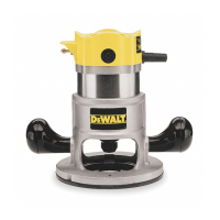
Set‑up: Fixed and D–Handle Base
Motor Quick Release (Fig. A)
1. Open the locking lever
4
on thebase.
2. Grasp the base with one hand while depressing the quick
release latches
1
.
3. With the other hand, grasp the top of the motor unit and
lift it from thebase.
Inserting the Motor into the Base
(Fig. A, C, D, H)
1. Open the locking lever
4
on thebase.
2. Thread the depth adjustment ring
2
onto the motor
until the ring is about halfway between the top and
bottom of the motor. Insert the motor into the base
by aligning the groove on the motor
8
with the guide
pins
23
on the base. Slide the motor down until the
depth adjustment ring snaps into the quick release
latches
1
.
NOTE: Guide pin grooves are located on either side of the
motor so that it can be positioned in twoorientations.
3. Close the locking lever when the desired depth is
achieved. For in formation on setting cutting depth, refer
to Adjusting the Depth ofCut.
For D–Handle Base Only (Fig.H)
1. Be sure that the trigger switch
13
is released and
the trigger lock button
14
is in the unlocked and
offposition.
2. Unlock and disconnect the detachable cordset
11
from
themotor.
3. Connect the detachable cordset
11
to bottom of
D‑Handle and lock thecord.
to load the motor, you could damage the motor by
overheating. Reduce the depth of cut and/or slow the
feed rate to prevent tooldamage.
SPEED SELECTION CHART
DIAL SETTING APPROX. RPM
1 8000
2 12000
3 14000
4 18000
5 21000
6 24000
The speeds in this chart are approximate and are for
reference only. Your router may not produce the exact speed
listed for the dialsetting.
WARNING: Always follow the bit manufacturer’s speed
recommendations as some bit designs require specific
speeds for safety orperformance.
If you are unsure of the proper speed or are experiencing any
type of problem, contact the bitmanufacturer.
 Loading...