14
E N G L I S H
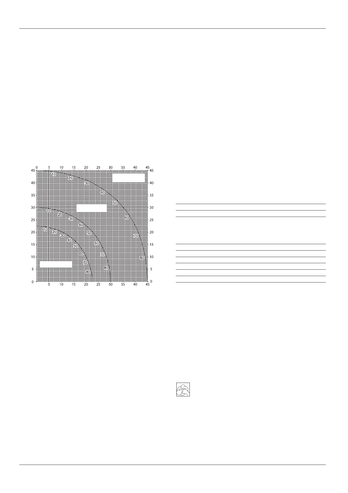
• Example: To make a 4 sided box with 25° exterior angles (angle “A”)
(fig. P2), use the upper right arc. Find 25° on the arc scale. Follow the
horizontal intersecting line to either side to get the mitre angle setting
on the saw (23°). Likewise follow the vertical intersecting line to the top
or bottom to get the bevel angle setting on the saw (40°). Always try
cuts on a few scrap pieces of wood to verify the settings on the saw.
Vernier scale (fig. Q1 - Q3)
Your saw is equipped with a vernier scale for added precision. For settings
that require partial degrees (
1
/
4
°,
1
/
2
°,
3
/
4
°), the vernier scale allows you to
accurately set mitre angles to the nearest
1
/
4
° (15 minutes). To use the
vernier scale follow the steps listed below.
As an example, assume that the angle you want to mitre is 24
1
/
4
° right.
• Switch off the mitre saw.
• Set the mitre angle to the nearest whole degree desired by aligning the
centre mark in the vernier scale, shown in fig. Q1, with the whole
degree number etched in the mitre scale. Examine fig. Q2 closely;
the setting shown is 24° right mitre.
• To set the additional
1
/
4
°, squeeze the mitre arm lock and carefully
move the arm to the right until the
1
/
4
° vernier mark aligns with the
closest degree mark on the mitre scale.
In this example, the closest degree mark on the mitre scale happens to
be 25°. Fig. Q3 shows a setting of 24
1
/
4
° right mitre.
• When mitring to the right:
- increase the mitre angle by moving the arm to align the appropriate
vernier mark with the closest mark on the mitre scale to the right.
- decrease the mitre angle by moving the arm to align the appropriate
vernier mark with the closest mark on the mitre scale to the left.
SET THIS BEVEL ANGLE ON SAW
WASNOELGNARETIMSIHTTES
)"A"ELGNA(XOBFOEDISFOELGNA
SQUARE BOX
6 SIDED BOX
8 SIDED BOX
• When mitring to the left:
- increase the mitre angle by moving the arm to align the appropriate
vernier mark with the closest mark on the mitre scale to the left.
- decrease the mitre angle by moving the arm to align the appropriate
vernier mark with the closest mark on the mitre scale to the right.
Cutting crown mouldings
The cutting of crown moulding is performed in a compound mitre. In order
to achieve extreme accuracy, your saw has pre-set angle positions at
31,62° mitre and 33,85° bevel. These settings are for standard crown
mouldings with 52° angles at the top and 38° angles at the bottom.
Dust extraction (fig. A2 & A3)
• Fit the dustbag (24) onto the dust spout (16).
• Whenever possible, connect a dust extraction device designed in
accordance with the relevant regulations regarding dust emission.
Saw blades
To obtain the stated cutting capacities, always use 305 mm saw blades
with 25.4 mm arbor holes.
Cutting non-ferrous metals
When cutting non-ferrous metals, the machine is only to be used in the
mitre saw mode. We recommend that bevel and compound mitre cuts
should not be performed in non-ferrous metals. The machine is not to be
used for cutting ferrous metals.
• Always use a material clamp when cutting non-ferrous metals.
Make sure that the workpiece is clamped securely.
• Only apply saw blades that are qualified for cutting non-ferrous metals.
• When using lubricants, only apply wax or separation spray. Do not use
emulsions or similar fluids.
• Connect an FI or DI switch between machine and mains to avoid
residual risks caused by metal swarf.
The FI switch should comply with the following specifications:
V052egatlovdetar
A61tnerrucdetar
sm51<emitnoitcaer
Am03tnerrucgnisuf
The DI switch should comply with the following specifications:
DIN VDE 0661
V052egatlovdetar
A61tnerrucdetar
Am03tnerrucgnisuf
EP+N+Lffotucelop-lla
PE monitoring
low-voltage release
Optional accessories
Consult your dealer for further information on the appropriate accessories.
Transporting (fig. B)
In order to conveniently carry the mitre saw, a carrying handle (9) has been
included on the top of the saw arm.
• To transport the saw, lower the arm and depress the lock down pin (18).
• Always use the carrying handle (9) or the hand indentations (22) shown
in fig. B to transport the saw.
Maintenance
Your DEWALT power tool has been designed to operate over a long
period of time with a minimum of maintenance. Continuous satisfactory
operation depends upon proper tool care and regular cleaning.
Cleaning
Keep the ventilation slots clear and regularly clean the housing with a soft
cloth.
• Regularly clean the table top.
• Regularly clean the dust collection system.

 Loading...