주:
모재 제거 게이지에서 권장한 여러 너비의 재료에
경고: 모재를 둔 채로 공구의 전원을 켜지
마십시오. 크게 다칠 수 있습니다.
주: 자동대패가 작동할 때에만 속도를 내십시오.
본 자동대패는 두 가지 속도로 재료를 공급할 수 있습니다.
모재의 두께를 보다 빠르게 제거하려면 속도
을 권장합니다. 저속으
로 칼이 닳고, 인치당 179 절단을 함으로 찢겨지는 것을 줄여줄 것입니다.
각각 권장한 절삭 깊이를 초과하지 마십시오.
속도 선택
깎을 때 효율을 높이고, 다양한 재료의 표면을 최상으로
마감하기 위해서 2단 변속기(P)가 고안되었습니다.
“
2
”
로 맞추십시오. 그렇게 하면 인치 당 96번의
절단을 합니다. 마감질을 하려면 속도
“
1
”
로 맞추십시오. 속도
“
1
”
은 최종 두께로 맞추기 전
에 마지막으로 왕복하면서 미세하게 마감하는데 있어 이상적인 속도입니다.
주: 아주 딱딱하거나 무늬가 있는 목재를 평평하게 깎을 때, 속도
“
1
”
팬-보조 부스러기 배출 시스템
자동대패에는 환풍 시스템이 장착되어 있어 공구에서 부스러기를배출하도록 해줍니다.
환풍 시스템은 별도의 방진 시스템과 함께 사용하게 될 것입니다.
DW735에 저사양청소기에 연결하는 것은 권장하지
주:
않습니다. 대부분의 진공청소기들은 대패질을 하는 동안
배출되는 부스러기의 양을 감당하지 못합니다. 부스러기들이
흡수되지 않도록 진공 호스가 막힐 수 있습니다.
보다 자세한 사항은 제 12쪽의 문제점 해결가이드를
보십시오.
자동 왕복대 잠금
본 자동대패에는 수동 왕복대 잠금이 없습니다. 대패질을 하는 동안 움직임을 자동으로
최소화 하는 이 장치는 4개의 나사산 위치에 있습니다.
19
터릿 조정장치
본 자동대패에는 미리 설정해놓은 깊이로 반복적으로 대패질을 할 때 사용하는 터릿 조정장
치(Q)가 있습니다. 이 장치는
3mm(1/8”), 6.5mm(1/4”), 12,5mm(1/2”), 19mm(3/4”), 25,5mm(1”),
32mmm(1-1/4”)
로 설정되어 있습니다.
주: 터릿 조장장치 눈금보다 작게 왕복대를 크랭크하도록 무리해서 사용하지
마십시오. 평삭기의 높이 조정 시스템에 영구적인 손상이 있을 것입니다.
터릿 조정장치로 왕복대가 할 수 있는 최소 깊이 설정하기
1. 터릿 조정장치를 설정하기 전에 왕복대가
32mm(1-1/4”)
이상으로 설정되어 있는지 확인
하십시오.
2. 빨간색 지침이 원하는 두께를 가리킬 때까지 평삭기의 좌측 앞쪽에 있는 다이얼을
돌리고 나서 왕복대를 내려주십시오.
3. 올바른 최종 두께가 될 때까지 원하는 만큼 작업대상물을 깎아내십시오.
기본적인 대패질하기
올바른 대패질 방법
재료를 대패질하기
1. 첫 번째 대패질에서 원하는 높이만큼 왕복대를 낮춰
주십시오.
2. 공구의 전원을 켜고 공급 롤러에 재료를 넣으십시오.
3. 마무리된 절단면을 살펴보고, 다음 번 대패질에 적절한
높이로 왕복대를 조정하십시오.
주:‘올바른 대패질 방법’에서 권장한 대로 각 대패질 사이에 보드를 앞뒤로
가볍게 쳐주십시오.
보다 자세한 사항은 제 12쪽의 문제점 해결가이드를 보십시오.
경고: 모재가 이미 왕복대 아래 끼워진 상태에서 공구의 전원을 켜지 마십
시오. 모재를 공구에 넣기 전에 롤러와 커터 헤드의 속도가 완전히 올라갈 때
까지 기다리십시오.
6
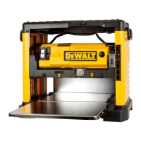
NOTE: Do not exceed the recommended depth of cut
for various widths of material recommended on the
material removal gauge.
WARNING: DO NOT SWITCH THE UNIT ON
WITH THE MATERIAL POSITIONED UNDER THE
CARRIAGE. SERIOUS INJURY COULD RESULT.
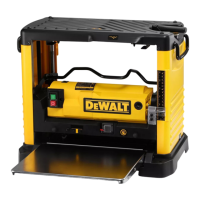
SPEED SELECTION
NOTE: ONLY SWITCH SPEEDS WHEN THE
PLANER IS RUNNING.
Your planer has the ability to feed material at two different speeds. The two-speed feature
(P) was designed to improve efficiency when planing and to provide the best possible
surface finish to a variety of materials.
To remove material thickness more quickly, set the unit at speed “2”. This setting deliv-
ers 96 cuts per inch to the material. For finishing, set the unit to speed “1”. Speed “1” is
ideal for ensuring the finest finish on the last pass before your final thickness is achieved.
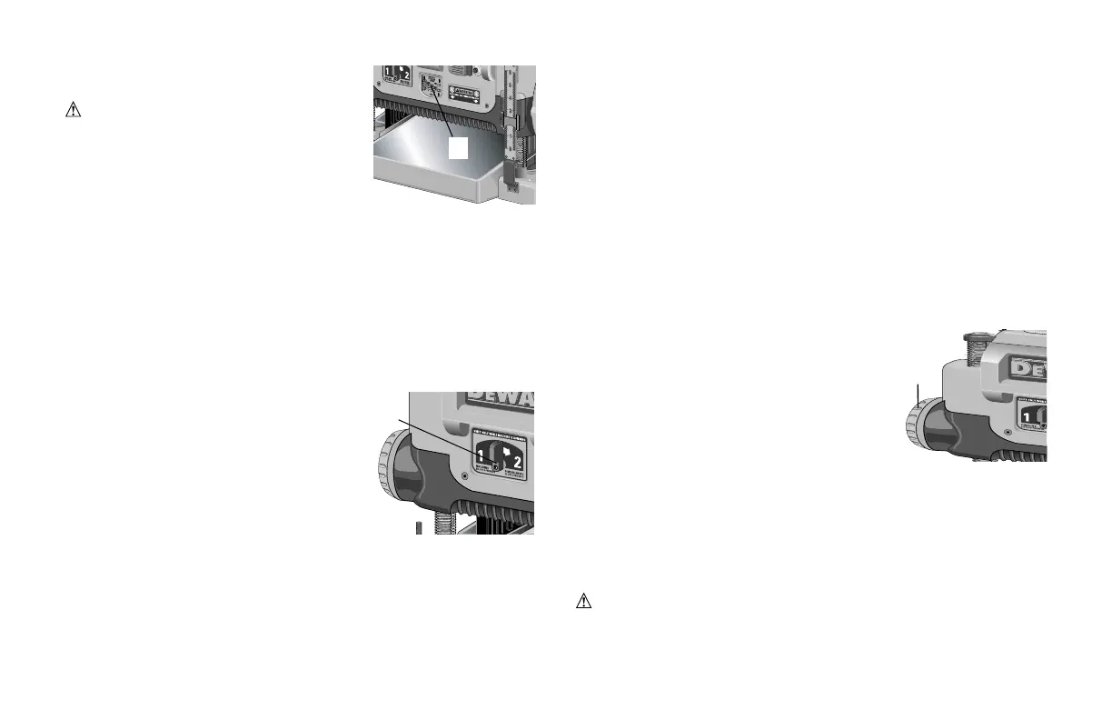
NOTE: When planing particularly hard or figured species of wood, speed “1” is rec-
ommended. The slower feed rate will reduce knife wear and tear-out by delivering 179
cuts per inch to the material.
FAN-ASSISTED CHIP EJECTION SYSTEM
Your planer is equipped with a fan-assisted chip ejection system to aid in exhausting
chips from the unit. The fan-assisted chip ejection system will work in conjunction
with independent dust collection systems.
NOTE: It is not recommended that a shop vac be
connected to the DW735. The capacity of most vacs
does not support the volume of chips ejected during
planing. The vacuum hose may clog stopping the flow
of chips.
See the Troubleshooting Guide, page 12, for additional
information.
AUTOMATIC CARRIAGE LOCK
There is no manual carriage lock on your planer. A device that automatically minimiz-
es the movement that causes snipe during planing is designed into the four threaded
posts.
TURRET STOP
Your planer is equipped with a turret stop (Q) for repetitive planing at pre-set depths.
Stops are set at 3mm (1/8”), 6.5mm (1/4”), 12.5mm (1/2”), 19mm (3/4”), 25.5mm
(1”), and 32mm (1-1/4”).
NOTE: DO NOT USE FORCE TO CRANK THE CARRIAGE BELOW THE LEVEL
THAT THE TURRENT STOP INDICATES. PERMANENT DAMAGE TO THE HEIGHT
ADJUSTMENT SYSTEM ON YOUR PALANER WILL RESULT.
TO SET THE MINIMUM DEPTH TO WHICH THE CARRIAGE CAN TRAVEL WITH
THE TURRET STOP
1. Be sure the carriage is set above 32mm(1-1/4”) before trying to set the turret
stop.
2. Turn the dial on the front left of the planer until the desired thickness setting
aligns with the red indicator then lower the car-
riage.
3. Plane the workpiece at desired increments until
the correct final thickness is achieved.
PLANING BASICS
PROPER PLANING TECHNIQUE
TO PLANE YOUR MATERIAL
1. Lower the carriage to the desired height for your first pass.
2. Turn the unit on and feed the material into the feed rollers.
3. Examine the finished cut and adjust the carriage to the appropriate height for
your next pass.
NOTE: Flip the board back and forth between each pass as
recommended in Proper Planing Techniques.
See the Troubleshooting Guide, page 12, for additional information.
WARNING: DO NOT TURN THE UNIT ON WITH THE MATERIAL ALREADY
INSERTED UNDER THE CARRIAGE. WAIT UNTIL THE ROLLERS AND CUTTER
HEAD ARE UP TO FULL SPEED BEFORE FEEDING YOUR MATERIAL INTO THE
P
Q
O
6
NOTE: Do not exceed the recommended depth of cut
for various widths of material recommended on the
material removal gauge.
WARNING: DO NOT SWITCH THE UNIT ON
WITH THE MATERIAL POSITIONED UNDER THE
CARRIAGE. SERIOUS INJURY COULD RESULT.
SPEED SELECTION
NOTE: ONLY SWITCH SPEEDS WHEN THE
PLANER IS RUNNING.
Your planer has the ability to feed material at two different speeds. The two-speed feature
(P) was designed to improve efficiency when planing and to provide the best possible
surface finish to a variety of materials.
To remove material thickness more quickly, set the unit at speed “2”. This setting deliv-
ers 96 cuts per inch to the material. For finishing, set the unit to speed “1”. Speed “1” is
ideal for ensuring the finest finish on the last pass before your final thickness is achieved.
NOTE: When planing particularly hard or figured species of wood, speed “1” is rec-
ommended. The slower feed rate will reduce knife wear and tear-out by delivering 179
cuts per inch to the material.
FAN-ASSISTED CHIP EJECTION SYSTEM
Your planer is equipped with a fan-assisted chip ejection system to aid in exhausting
chips from the unit. The fan-assisted chip ejection system will work in conjunction
with independent dust collection systems.
NOTE: It is not recommended that a shop vac be
connected to the DW735. The capacity of most vacs
does not support the volume of chips ejected during
planing. The vacuum hose may clog stopping the flow
of chips.
See the Troubleshooting Guide, page 12, for additional
information.
AUTOMATIC CARRIAGE LOCK
There is no manual carriage lock on your planer. A device that automatically minimiz-
es the movement that causes snipe during planing is designed into the four threaded
posts.
TURRET STOP
Your planer is equipped with a turret stop (Q) for repetitive planing at pre-set depths.
Stops are set at 3mm (1/8”), 6.5mm (1/4”), 12.5mm (1/2”), 19mm (3/4”), 25.5mm
(1”), and 32mm (1-1/4”).
NOTE: DO NOT USE FORCE TO CRANK THE CARRIAGE BELOW THE LEVEL
THAT THE TURRENT STOP INDICATES. PERMANENT DAMAGE TO THE HEIGHT
ADJUSTMENT SYSTEM ON YOUR PALANER WILL RESULT.
TO SET THE MINIMUM DEPTH TO WHICH THE CARRIAGE CAN TRAVEL WITH
THE TURRET STOP
1. Be sure the carriage is set above 32mm(1-1/4”) before trying to set the turret
stop.
2. Turn the dial on the front left of the planer until the desired thickness setting
aligns with the red indicator then lower the car-
riage.
3. Plane the workpiece at desired increments until
the correct final thickness is achieved.
PLANING BASICS
PROPER PLANING TECHNIQUE
TO PLANE YOUR MATERIAL
1. Lower the carriage to the desired height for your first pass.
2. Turn the unit on and feed the material into the feed rollers.
3. Examine the finished cut and adjust the carriage to the appropriate height for
your next pass.
NOTE: Flip the board back and forth between each pass as
recommended in Proper Planing Techniques.
See the Troubleshooting Guide, page 12, for additional information.
WARNING: DO NOT TURN THE UNIT ON WITH THE MATERIAL ALREADY
INSERTED UNDER THE CARRIAGE. WAIT UNTIL THE ROLLERS AND CUTTER
HEAD ARE UP TO FULL SPEED BEFORE FEEDING YOUR MATERIAL INTO THE
P
Q
6
NOTE: Do not exceed the recommended depth of cut
for various widths of material recommended on the
material removal gauge.
WARNING: DO NOT SWITCH THE UNIT ON
WITH THE MATERIAL POSITIONED UNDER THE
CARRIAGE. SERIOUS INJURY COULD RESULT.
SPEED SELECTION
NOTE: ONLY SWITCH SPEEDS WHEN THE
PLANER IS RUNNING.
Your planer has the ability to feed material at two different speeds. The two-speed feature
(P) was designed to improve efficiency when planing and to provide the best possible
surface finish to a variety of materials.
To remove material thickness more quickly, set the unit at speed “2”. This setting deliv-
ers 96 cuts per inch to the material. For finishing, set the unit to speed “1”. Speed “1” is
ideal for ensuring the finest finish on the last pass before your final thickness is achieved.
NOTE: When planing particularly hard or figured species of wood, speed “1” is rec-
ommended. The slower feed rate will reduce knife wear and tear-out by delivering 179
cuts per inch to the material.
FAN-ASSISTED CHIP EJECTION SYSTEM
Your planer is equipped with a fan-assisted chip ejection system to aid in exhausting
chips from the unit. The fan-assisted chip ejection system will work in conjunction
with independent dust collection systems.
NOTE: It is not recommended that a shop vac be
connected to the DW735. The capacity of most vacs
does not support the volume of chips ejected during
planing. The vacuum hose may clog stopping the flow
of chips.
See the Troubleshooting Guide, page 12, for additional
information.
AUTOMATIC CARRIAGE LOCK
There is no manual carriage lock on your planer. A device that automatically minimiz-
es the movement that causes snipe during planing is designed into the four threaded
posts.
TURRET STOP
Your planer is equipped with a turret stop (Q) for repetitive planing at pre-set depths.
Stops are set at 3mm (1/8”), 6.5mm (1/4”), 12.5mm (1/2”), 19mm (3/4”), 25.5mm
(1”), and 32mm (1-1/4”).
NOTE: DO NOT USE FORCE TO CRANK THE CARRIAGE BELOW THE LEVEL
THAT THE TURRENT STOP INDICATES. PERMANENT DAMAGE TO THE HEIGHT
ADJUSTMENT SYSTEM ON YOUR PALANER WILL RESULT.
TO SET THE MINIMUM DEPTH TO WHICH THE CARRIAGE CAN TRAVEL WITH
THE TURRET STOP
1. Be sure the carriage is set above 32mm(1-1/4”) before trying to set the turret
stop.
2. Turn the dial on the front left of the planer until the desired thickness setting
aligns with the red indicator then lower the car-
riage.
3. Plane the workpiece at desired increments until
the correct final thickness is achieved.
PLANING BASICS
PROPER PLANING TECHNIQUE
TO PLANE YOUR MATERIAL
1. Lower the carriage to the desired height for your first pass.
2. Turn the unit on and feed the material into the feed rollers.
3. Examine the finished cut and adjust the carriage to the appropriate height for
your next pass.
NOTE: Flip the board back and forth between each pass as
recommended in Proper Planing Techniques.
See the Troubleshooting Guide, page 12, for additional information.
WARNING: DO NOT TURN THE UNIT ON WITH THE MATERIAL ALREADY
INSERTED UNDER THE CARRIAGE. WAIT UNTIL THE ROLLERS AND CUTTER
HEAD ARE UP TO FULL SPEED BEFORE FEEDING YOUR MATERIAL INTO THE
P
 Loading...