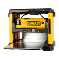
경고:
전원이 회로 차단기에 의해 차단되었다면,
자동대패 가 갑자기 가동되지 않도록 전원을 켜기 전에
스위치가 꺼져 있는지 확인하십시오.
본 자동대패의 배출 팬에 있는 부스러기를 정기적으로 제거하고 깨끗이 해야 합니다.
1. T형 렌치로 자동대패의 뚜껑을 여십시오.
자동대패를 다시 사용하기 전에 팬 하우징이 제대로 붙어 있는지, 먼지 덮개와
주:
날이 무딜 때 종종 회로 차단기가 과부하됩니다.
차단 기가 작동하지 않도록 정기적으로 날을 교체하십시오.
회로 차단기를 다시 설정하고 대패질을 계속하기 전에 날을
확인 하십시오.
드라이브 벨트 교체하기
DEWALT 인증 서비스 센터에서 드라이브 벨트를 구매하실 수 있습니다. 전문 수리기사가
드라이브 벨트를 교체해야 합니다.
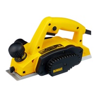
부스러기 배출 팬
주: 부스러기 배출 팬을 만지려면 전원을 끄고 플러그를 뽑으십시오.
팬 다루기
2. 먼지 덮개(그림 2, 3)를 꺼내 옆에 두십시오.
3. 팬 하우징 주변의 나사를 풀으십시오.
4. 그림과 같이 팬 하우징을 꺼내 옆에 두십시오. 팬이 이제
드러날 것입니다.
보다 자세한 사항은 제 12쪽의 문제점 해결가이드를 보십시오.
경고:
뚜껑이 바르게 조립되었는지 확인하십시오.
부속품
판매자나 지역 서비스 센터에서 본 전동공구에 권장하는 부속품을 구매하실 수 있습니다.
DW735 평삭기에는 4 가지 부속품이 있습니다.
·
DW7350
이동형 스탠드(호주 및 뉴질랜드 미포함)
·
DW7351
접이식 테이블(호주 및 뉴질랜드 미포함)
·
DW7352 330mm(13’’)
날
·
DW7353
부스러기 배출 부속품
주의: 본 전동공구에 권장하지 않은 기타 부속품을 사용하면 위험할 수 있습니다.
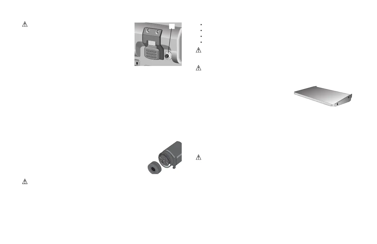
DW7351 접이식 테이블
경고: 안전을 위해, 테이블을 부착하기 전에 사용설명서를 읽으십시오. 이 경고에
따르지 않으면 다치거나 자동대패와 부속품이 크게 손상될 수 있습니다. 본 공구를
손볼 때에는 동일한 교체품 만을 사용하십시오. 손상된 코드는 인증된 서비스
센터에서 교 체하십시오.
DW7351 접이식 테이블에는 다음 부품들이
포함되어 있습니다:
접이식 작업대 2 알렌 캡 나사 4
스프링 4 너트 4
계단형 알렌 볼트 4
바닥장치의 설정 및 설치
1. 안전한 작업대 및 테이블에 자동대패를 두십시오. 바닥 앞쪽의
75-100mm(3-4’’)
가 아래쪽에
닿을 수 있도록 평삭기를 두십시오.
2. 테이블에서 기울어지거나 떨어지지 않도록 못이나 나사로 자동대패의 뒷부분을 작업대/
접이식 테이블이 설치된 곳의 양 끝이 제대로 고정되어 있지 않으면 자동대패가
테이블에서 기울어지거나 떨어질 수 있습니다. 그러면 크게 다칠 수 있습니다.
5. 자동대패 아랫부분의 첫 번째 홈에 있는 구멍으로 계단형 알렌 볼트를 밀어넣으십시오.
6. 자동대패 아랫부분에서 렌치를 사용하여 계단형 볼트가 돌아가면서 너트를 그 자리에
테이블에 고정하십시오.
경고:
3. 계단형 알렌 볼트의 작은 쪽에 스프링을 두십시오.
4. 스프링이 있는 볼트의 끝부분이 공구 바닥면의 큰 구멍에 들어가게 하십시오.
스프링이 그 홈에 가볍게 맞아야 하며, 나사산은 그 홈의 오른쪽에 보여야 합니다.
고정시켜야 합니다. T형 렌치를 사용하여 계단형 볼트가 완전히 고정될 때까지 돌릴 수
있습니다(그림 7).
7. 작은 알렌 나사를 바닥면의 아래쪽 나사산 구멍에 놓으십시오. T형 렌치를 이용하여
확실히 조여주십시오(그림 8).
23
10
the reset button (X) before you resume working.
WARNING: To prevent the planer from starting
unexpectedly if power is interrupted by a circuit breaker
trip, make sure the switch is in the OFF position before
restoring power.
NOTE: Circuit breaker overload is often the result of dull
knives. Change your knives on a regular basis to avoid
tripping your breaker. Check your knives before re-setting
the circuit breaker and continuing to plane.
See the Troubleshooting Guide on page 12 for additional information on circuit breaker
trips.
REPLACING THE DRIVE BELT
Drive belts are available at extra cost at DEWALT authorized service centers.
Replacement of the drive belt should be performed by qualified service personnel.
CHIP EJECTION FAN
The chip ejection fan on your planer should be cleaned or cleared of debris periodi-
cally.
NOTE: TURN OFF AND UNPLUG THE PLANER PRIOR TO ACCESSING THE CHIP EJECTION FAN.
TO ACCESS THE FAN
1. Remove the top cover of the planer with the T-wrench.
2. Remove the dust shroud (Fig. 2, 3) and place it aside.
3. Remove the screws around the fan housing.
4. Remove the fan housing and place it aside as shown.
The fan will now be exposed for cleaning.
See the Troubleshooting Guide, page 12, for additional informa-
tion.
WARNING: Be sure to properly attach the fan housing and assemble the shroud
and top cover correctly before using your planer again.
ACCESSORIES
Recommended accessories for use with your tool are available at extra cost from your
distributor or local service center.
Four accessories are available for the DW735 Thickness Planer.
• DW7350 Mobile Stand (Not for Australia or New Zealand).
• DW7351 Folding Tables (Not for Australia or New Zealand).
• DW7352 330mm(13”) Knives.
• DW7353 Chip Ejection Accessory.
CAUTION: The use of any other accessory not recommended for use with this
tool could be hazardous.
I
DW7351 ACCESSORY FOLDING TABLES
WARNING: For your own safety, read the tool instruction manual before attaching
the tables. Failure to heed these warnings may result in personal injury and serious
damage to the planer and the accessory. When servicing this tool, use only identical
replacement parts. Have damaged cords replaced
by an authorized service center.
Your DW7351 folding table box should include:
2 folding tables 4 Allen cap screws
4 springs 4 nuts
4 stepped Allen bolts
SET-UP AND INSTALLATION OF BASE HARDWARE
1. Place planer on a secure table or workbench. Position planer so the front
75-100mm(3-4”) of the base can be accessed from the underside.
2. Secure the rear of the planer to the table/bench with nails or screws to prevent it
from tilting or falling from the table.
WARNING: The planer could tilt or fall from the table if it is not properly secured
opposite the end where the folding table is being installed. Serious injury may result.
3. Place the spring onto the small end of the stepped Allen bolt.
4. Insert the end of the bolt with the spring around it into the larger hole on the side
of the base.
5. Push the stepped Allen bolt all the way through the hole in the first rib on the
underside of the planer. The spring should engage the rib slightly and the threads
should show on the right side of the rib.
6. On the underside of the planer, use a wrench to hold the nut in place while turn-
ing the stepped bolt into it. The T-wrench on your planer can be used to turn the
stepped bolt until it is fully secured (Fig. 7).
7. Install the smaller Allen screw into the lower threaded hole on the side of the
X
 Loading...