5
English
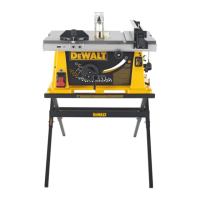
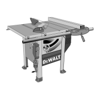
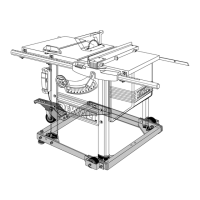
FEATURES (Fig. 3, 4)
Examine Figures 3 and 4 to become familiar with the saw and its various parts. The following
sections on assembly and adjustments will refer to these terms and you must know what
and where the parts are.
FIGURE 3
A. Table G. Bevel lock lever
B. Blade H. Circuit breaker button
C. Rip scale indicator I. ON/OFF switch
D. Fine adjust knob J. Mounting holes
E. Rail lock lever K. Miter gauge
F. Blade height adjustment wheel L. Screw down holes
FIGURE 4
M. Blade guard assembly R. Rip fence rear latch
N. Blade guard lock lever S. Arbor wrench, spindle wrench
O. Riving knife T. Work Support Extension (retracted)
P. Anti-kickback assembly U. Push stick
Q. Dust collection port
ASSEMBLY
WARNING: Shock Hazard. To reduce the risk of serious personal injury, turn unit
off and disconnect machine from power source before attempting to move it, change
accessories or make any adjustments. An accidental start-up can cause injury.
YOUR SAW SHOULD BE ASSEMBLED IN THE FOLLOWING ORDER:
1. Blade
2. Throat plate
3. Rip fence (NOTE: Adjust rip scale before proceeding. See Adjusting Rip Scale.)
4. Anti-kickback assembly
5. Blade guard assembly
Tools needed for assembly include the wrenches included with your saw.
ATTACHING/REPLACING THE BLADE
1. Raise the saw blade arbor to its maximum height by turning the blade height adjustment
wheel clockwise.
2. Remove the arbor nut (W) and flange from the saw arbor by turning counterclockwise.
FIG. 5A
W
X
V
XX
B
FIG. 3
A
K
L
J
E
G
I
F
D
C
H
B
FIG. 4
R
P
Q
T
S
M
O
N
U