Do you have a question about the DeWalt DW743N and is the answer not in the manual?
Defines severity levels for signal words like DANGER, WARNING, CAUTION, NOTICE.
Declares compliance with machinery directives and other EC directives.
Provides essential safety precautions for operating the tool in various environments.
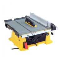
Instructions for safely removing the machine and its parts from the packaging.
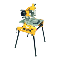
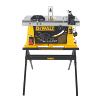
Details on attaching the legs for stand-alone placement of the machine.
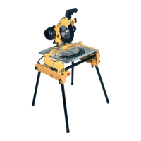
Instructions for fitting the under-table guard for mitre saw operation.
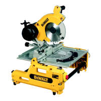
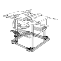
Steps to convert the machine from bench saw to mitre saw mode.
Detailed procedure for safely installing and replacing the saw blade.
How to ensure the blade is correctly aligned with the fence at 90 degrees.
How to ensure the blade is perpendicular to the table surface.
How to set and verify mitre angles accurately.
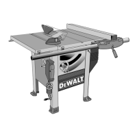
Instructions for correctly positioning the riving knife for bench saw mode.
How to attach the upper blade guard for bench saw operation.
General guidelines and warnings for operating the machine safely.
Procedures and precautions for making various cuts in mitre saw mode.
Guidelines for safe operation and workpiece handling in mitre saw mode.
Step-by-step instructions for making a straight cross cut.
How to set up and perform mitre cuts accurately.
Instructions for making angled cuts using the bevel function.
Information on performing combined mitre and bevel cuts.
Process for making rip cuts using the parallel fence.
How to perform bevel cuts while in bench saw mode.
Steps for setting up and performing mitre cuts in bench saw mode.
Instructions for connecting and using the dust extraction system.
How to mount and use optional supports for mitre sawing.
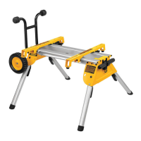
How to mount and use the roller support table for mitre or bench saw modes.
How to fit the side extension table to increase rip capacity.
Information on using the single sliding table for larger boards.
Information on using the double sliding table for larger board sizes.
Details on lubricating moving parts and bearings for optimal performance.
Details of the satisfaction guarantee policy for users.
Information about the free service contract offered for the tool.
Details of the warranty policy covering defects in materials and workmanship.
| Input power | 2000 W |
|---|---|
| Output power | 1550 W |
| Blade bore | 30 mm |
| Noise level | 106.5 dB |
| Blade diameter | 250 mm |
| Idle speed (max) | 2850 RPM |
| Cutting depth (45º) | 32 mm |
| Cutting depth (90º) | 70 mm |
| Depth | 700 mm |
|---|---|
| Width | 670 mm |
| Height | 750 mm |
| Weight | 37000 g |