4
English
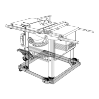
been damaged during shipping. If any parts are missing or damaged, contact your dealer to
replace them before attempting to assemble the tool.
Refer to Figure 2 for the loose items and hardware included with the saw:
1. Rip fence
2. Arbor wrench and spindle wrench (attached to saw base)
3. Blade guard
4. Miter gauge
5. Push stick (attached to saw base)
6. Extra guard shims
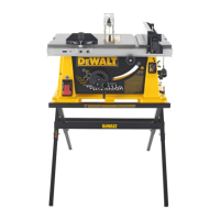
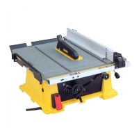
FEATURES (Fig. 3, 4)
Examine Figures 3 and 4 to become familiar with the saw and its various parts. The
following sections on assembly and adjustments will refer to these terms and you must know
what and where the parts are.
FIG. 3
A
B
D
E
F
G
H
I
N
J
K
M
L
N
O
P
C
Q
FIGURE 3
A. Table J. Bevel lock lever
B. Miter gauge K. ON/OFF switch
C. Blade L. Rip fence indicator
D. Blade guard M. Adjustable feet
E. Fence N. Mounting holes
F. Fence rails O. Cord wrap
G. Rip fence front latch P. Handle
H. Fine adjustment knob Q. Anti-kickback teeth
I. Blade height adjustment wheel
FIGURE 4
R. Rip fence rear latch
V. Arbor wrench, spindle wrench
S. Dust collection port W. Rail lock lever
T. Dust shroud
U. Push stick
• lead from lead-based paints,
• crystalline silica from bricks and cement and other masonry products, and
• arsenic and chromium from chemically-treated lumber (CCA).
Your risk from these exposures varies, depending on how often you do this type of work.
To reduce your exposure to these chemicals: work in a well-ventilated area, and work with
approved safety equipment, such as those dust masks that are specially designed to filter
out microscopic particles.
• Avoid prolonged contact with dust from power sanding, sawing, grinding,
drilling, and other construction activities. Wear protective clothing and wash
exposed areas with soap and water. Allowing dust to get into your mouth, eyes, or
lay on the skin may promote absorption of harmful chemicals.
WARNING: Use of this tool can generate and/or disburse dust, which may cause
serious and permanent respiratory or other injury. Always use NIOSH/OSHA approved
respiratory protection appropriate for the dust exposure. Direct particles away from face
and body. Always operate tool in well-ventilated area and provide for proper dust removal.
Use dust collection system wherever possible.
SAVE THESE INSTRUCTIONS FOR FUTURE USE
Specifi cations
15 AMP
Miter Angle 60° L and R
Bevel Angle 0° to 45° L
Blade Size 10" (254 mm)
Max. Cut Depth 0° Bevel 3-1/8" (79 mm)
Max. Cut Depth 45° Bevel 2-1/4" (57 mm)
RPM, no load 3850
6
FIG. 1 FIG. 2
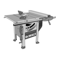
Unpacking
WARNING: To reduce the risk of injury, do not connect the machine to the power source
until the machine is completely assembled and you read and understand the entire
instruction manual.
Open the box and slide the saw out, as shown in Figure 1. Carefully unpack the table saw
and all loose items from the carton. Examine all parts to make sure that parts have not