Do you have a question about the DeWalt DW876 and is the answer not in the manual?
Provides detailed specifications including motor power, speed, blade dimensions, table size, and weight.
Confirms compliance with relevant EU directives and standards for power tools.
Covers general safety practices like keeping the work area clean, personal protection, and proper tool usage.
Specific safety guidelines for operating bandsaws, including blade handling and guard usage.
Identifies inherent risks that remain even with safety precautions in place, such as noise and dust exposure.
Lists all components included in the product packaging, including the machine, legstand, and accessories.
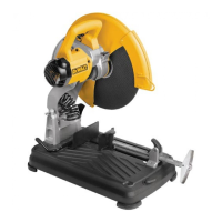
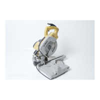
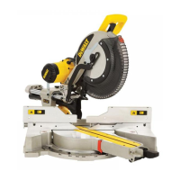
Details the various parts of the DW876 bandsaw and its intended professional workshop applications.
Instructions for safely replacing the mains plug on the tool, emphasizing proper wiring and fuse rating.
Guidance on selecting and using appropriate extension cables for the power tool, including conductor size and cable length.
Step-by-step instructions for assembling the legstand components using the provided fasteners.
Procedure for correctly positioning and securing the table top onto the legstand for optimal blade performance.
Detailed steps for safely installing a new saw blade, including tensioning and alignment.
Explains how to adjust the blade tension using the tensioner and scale for correct blade width.
Instructions for centering the saw blade on the upper band wheel for proper operation.
Guides for setting blade guide blocks and rear support bearings to control blade movement and alignment.
Steps for attaching and aligning the rip fence to the bandsaw table for straight cuts.
Procedure for installing and using the adjustable mitre fence for angled cuts.
Instructions on how to tilt the table and set it to the desired bevel angle, including for 90° cuts.
Guidance on positioning the blade guard approximately 10 mm above the workpiece surface.
Explains how to change the drive belt to select between low and high speeds for different cutting tasks.
Details the operation of the ON/OFF switch and the conditions for continuous operation.
Basic guidance on performing cuts, emphasizing proper blade guard positioning.
Instructions for performing ripping cuts using the rip fence, including workpiece feed and push stick usage.
Steps for setting the angle on the mitre fence and performing mitre cuts.
Instructions on setting the table angle and performing bevel cuts.
Explains how to perform a cut that combines both mitre and bevel angles.
Guidance on performing freehand cuts without a fence, and limitations on curve cutting.
Information on connecting a dust extraction device to the machine for dust management.
General advice on maintaining the power tool for optimal performance and longevity.
Details the 30-day satisfaction guarantee, requiring proof of purchase for refund or exchange.
Explains the free service contract for 12 months following purchase, covering labor and spare parts.
Outlines the warranty terms covering defective parts due to materials or workmanship within 12 months.
| Power Output | 750 W |
|---|---|
| Voltage | 230 V |
| Motor | Induction |
| Blade Speed | 0 - 85 m/min |
| Max Cutting Depth | 200 mm |
| Max Cut Capacity at 90° | 127 mm |
| Cutting Capacity (Square) | 4-3/4 inches |
| Cutting Capacity (Round) | 200 mm |
| Table Size | 500 x 500 mm |