ENGLISH
8
Fig. C
7
12
13
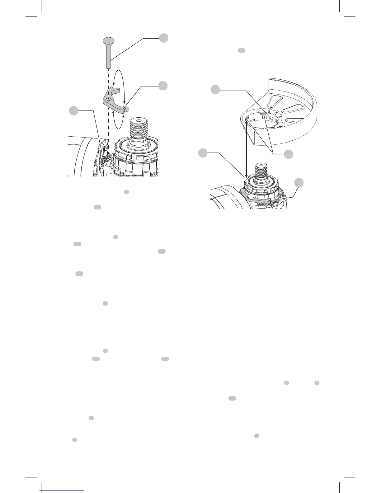
Setting Guard Adjustment Options
To adjust the guard release lever
7
for desired
adjustmentoption:
1. Remove screw
12
using a T20bit.
2. Remove the guard release lever taking note of the
spring position. Choose the end of the lever for the
desired adjustment option. One-touch will use the
slanted end of the lever
7
to engage the alignment
holes
14
on the guard collar. Two-touch will use the
squaredend to engage the alignment holes
14
on the
guardcollar.
3. Replace the lever, positioning the chosen end under the
spring
13
. Ensure the lever is in proper contact with
thespring.
4. Replace screw and torque to 2.0-3.0N-m. Ensure proper
installation with spring return function by depressing
guard release lever
7
.
Mounting Guard (Fig. D)
CAUTION: Prior to mounting guard, ensure the screw,
lever, and spring are fitted correctly before mounting
theguard.
1. With the spindle facing the operator, press and hold the
guard release lever
7
.
2. Align the lugs
15
on the guard with the slots
16
on
the gearcasecover.
3. Push the guard down until the guard lugs engage
and rotate them in the groove on the gear case cover.
Release the guard releaselever.
4. To position the guard:
One-touch
TM
: Rotate the guard clockwise into the
desired working position. Press and hold the guard
release lever
7
to rotate the guard in the counter-
clockwisedirection.
Two-touch
TM
: Press and hold the guard release
lever
7
. Rotate the guard clockwise or counter-
clockwise into the desired workingposition.
NOTE: The guard body should be positioned between
the spindle and the operator to provide maximum
operatorprotection.
The guard release lever should snap into one of the
alignment holes
14
on the guard collar. This ensures
that the guard issecure.
5. To remove the guard, follow steps 1–3 of these
instructions inreverse.
7
16
15
14
Fig. D
Flanges and Wheels
CAUTION: Turn unit off and unplug the tool before
making any adjustments or removing or installing
attachments oraccessories.
Mounting Non-Hubbed Wheels
(Fig. E, F)
WARNING: Failure to properly seat the flanges and/or
wheel could result in serious injury (or damage to the
tool or wheel).
CAUTION: Included flanges must be used with
depressed center Type 27/42 grinding wheels and
Type1/41 cutting wheels. See the Accessories Chart
for moreinformation.
WARNING: A closed, two-sided cutting wheel guard
is required when using abrasive cutting wheels or
diamond coated cuttingwheels.
WARNING: Use of a damaged flange or guard or fail-
ure to use proper flange and guard can re sult in injury
due to wheel breakage and wheel contact. See the
Accessories Chart for moreinformation.
1. Place the tool on a table, guardup.
2. Install the unthreaded backing flange
3
on spindle
1
with the raised center (pilot) facing thewheel.
3. Place wheel
17
against the backing flange,
centering the wheel on the raised center (pilot) of the
backingflange.
4. While depressing the spindle lock button and with the
hex depressions facing away from the wheel, thread the
threaded locking flange
4
on spindle so that the lugs
engage the two slots in thespindle.
NOTE: If the wheel you are installing is more than 1/8"
(3.17mm) thick, place the threaded locking flange on