ENGLISH
6
minimum wire size. The following table shows the correct
size to use depending on cord length and nameplate
ampere rating. If in doubt, use the next heavier gauge. The
lower the gauge number, the heavier thecord.
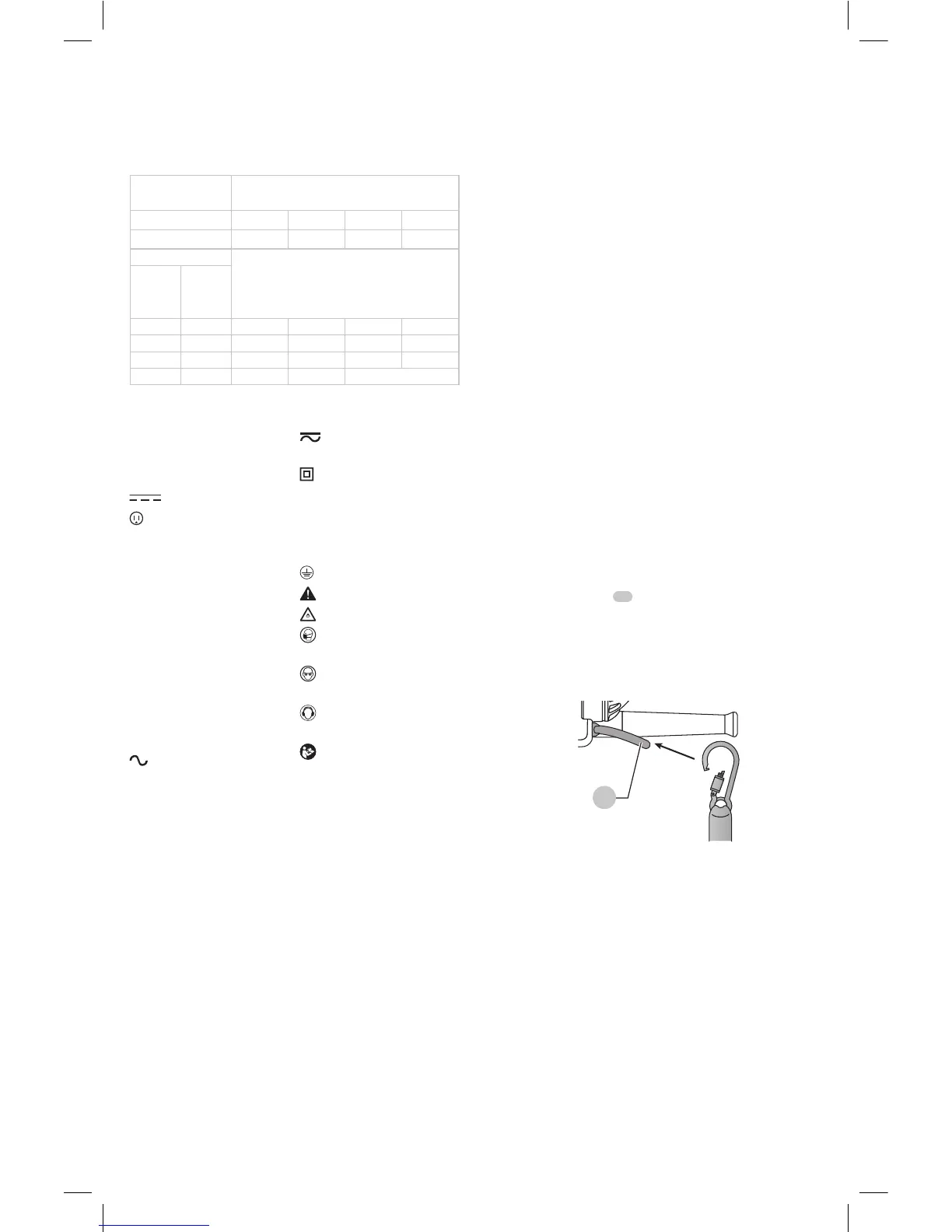
Minimum Gauge for Cord Sets
Volts
Total Length of Cord in Feet
(meters)
120 V 25 (7.6) 50 (15.2) 100 (30.5) 150 (45.7)
240 V 50 (15.2) 100 (30.5) 200 (61.0) 300 (91.4)
Ampere Rating
American Wire Gauge
More
Than
Not
More
Than
0 6 18 16 16 14
6 10 18 16 14 12
10 12 16 16 14 12
12 16 14 12 Not Recommended
The label on your tool may include the following symbols. The
symbols and their definitions are asfollows:
V ......................... volts
Hz .......................hertz
min ..................... minutes
or DC ......direct current
...................... Class I Construction
(grounded)
…/min ..............per minute
BPM ....................beats per minute
IPM ..................... impacts per minute
RPM .................... revolutions per
minute
sfpm ................... surface feet per
minute
SPM .................... strokes per minute
A ......................... amperes
W ........................watts
or AC ...........alternating current
or AC/DC .... alternating or
direct current
...................... Class II
Construction
(double insulated)
n
o
.......................no load speed
n .........................rated speed
......................earthing terminal
.....................safety alert symbol
.....................visible radiation
..................... wear respiratory
protection
..................... wear eye
protection
..................... wear hearing
protection
..................... read all
documentation
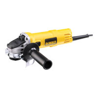
Lanyard Connection (Fig. B)
Safety Warnings Specific for Use At Height
• Always keep the tool and accessories tethered when
working "at height". [Maximum lanyard length: 6.5 ft
(2m)]
• Use only with lanyards appropriate for this tool type and
rated for at least 6.0 lbs (2.72 Kg).
• Crush, cut or entanglement hazard. Do not use near
moving parts, mechanisms or runningmachinery.
• Do not anchor the tool lanyard to anything on your body.
Anchor to a rigid structure that can withstand the forces
of a droppedtool.
• Make sure the lanyard is properly secure at each end prior
touse.
• Inspect tool and lanyard before each use for damage and
proper function (including fabric and stitching). Do not
use if damaged or not functioningproperly.
• Do not alter the lanyard connection or use in a manner
other than as instructed in thismanual.
• Only attach tool to a lanyard with a locking carabiner. Do
not attach by looping or knotting the lanyard. Do not use
rope orcord.
• Electrical shock hazard. Be sure power is off when working
in high voltage areas. Some lanyards areconductive.
• Dropped tools will swing on the lanyard, which could
cause injury or loss ofbalance.
• Do not carry the tool by attachment device or thelanyard.
• Do not attach more than one tool to eachlanyard.
• Only use appropriate
brand attachment point.
NEVER modify tools to create attachmentpoints.
• Only transfer the tool between hands while properly
balanced in a stableorientation.
• Do not attach lanyards to tool in a way that keeps guards,
switches or lock-offs from operatingproperly.
• Avoid getting tangled in thelanyard.
• Keep lanyard away from the cutting area of thetool.
• Do not use lanyards or attachment devices to get
additional leverage from thetool.
• Do not use for personal fallprotection.
• Falling object hazard! Only change accesories and
attachments where a dropped object won't cause a
hazard below you. Consult your AHJ or site supervisor for
procedures for working atheight.
• Use multi-action and screw gate type carabineers. Do not
use single action spring clipcarabineers.
The lanyard connection
11
is intended for use by
competent personnel, who are trained and knowledgeable
regarding working with tools in and around machinery and
"at height". A lanyard connection may be added to certain
models (DWE43114N, DWE43144N) by an authorized
servicecenter.
11
Fig. B
SAVE THESE INSTRUCTIONS FOR
FUTURE USE
Motor
Be sure your power supply agrees with the nameplate
marking. Voltage decrease of more than 10% will cause loss
of power and overheating.