ENGLISH
8
4. To position the guard:
One-touch
TM
: Rotate the guard clockwise into the
desired working position. Press and hold the guard
release lever
7
to rotate the guard in the counter-
clockwisedirection.
Two-touch
TM
: Press and hold the guard release
lever
7
. Rotate the guard clockwise or counter-
clockwise into the desired workingposition.
NOTE: The guard body should be positioned between
the spindle and the operator to provide maximum
operatorprotection.
The guard release lever should snap into one of the
alignment holes
14
on the guard collar. This ensures
that the guard issecure.
5. To remove the guard, follow steps 1–3 of these
instructions inreverse.
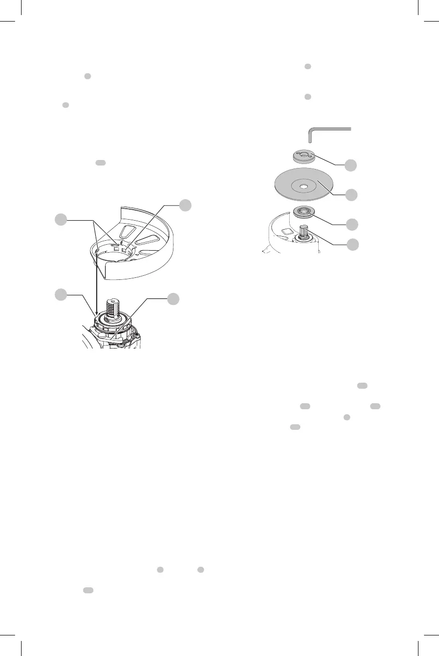
Fig. D
14
16
15
7
Flanges and Wheels
CAUTION: Turn unit off and unplug the tool before
making any adjustments or removing or installing
attachments oraccessories.
Mounting Non-Hubbed Wheels (Fig. E)
WARNING: Failure to properly seat the flanges and/or
wheel could result in serious injury (or damage to the
tool or wheel).
CAUTION: Included flanges must be used with
depressed center Type 27/42 grinding wheels and
Type1/41 cutting wheels. See the Accessories Chart
for moreinformation.
WARNING: A closed, two-sided cutting wheel guard
is required when using abrasive cutting wheels or
diamond coated cuttingwheels.
WARNING: Use of a damaged flange or guard or fail-
ure to use proper flange and guard can re sult in injury
due to wheel breakage and wheel contact. See the
Accessories Chart for moreinformation.
1. Place the tool on a table, guardup.
2. Install the unthreaded backing flange
3
on spindle
1
with the raised center (pilot) facing thewheel.
3. Place wheel
17
against the backing flange,
centering the wheel on the raised center (pilot) of the
backingflange.
4. While depressing the spindle lock button and with the
hex depressions facing away from the wheel, thread the
threaded locking flange
4
on spindle so that the lugs
engage the two slots in thespindle.
5. While depressing the spindle lock button, tighten the
threaded locking flange
4
using a HEX wrench.
6. To remove the wheel, depress the spindle lock button
and loosen the threaded lockingflange.
Fig. E
4
17
3
1
Mounting Sanding Backing Pads (Fig. A, F)
NOTE: Use of a guard with sanding discs that use backing
pads, often called fiber resin discs, is not required. Since a
guard is not required for these accessories, the guard may or
may not fit correctly ifused.
WARNING: Failure to properly seat the clamp nut
and/or pad could result in serious injury (or damage
to the tool or wheel).
WARNING: Proper guard must be reinstalled for
grinding wheel, cutting wheel, sanding flap disc,
wire brush or wire wheel applications after sanding
applications arecomplete.
1. Place or appropriately thread backing pad
19
on
thespindle.
2. Place the sanding disc
20
on the backing pad
19
.
3. While depressing spindle lock button
2
, thread the
sanding clamp nut
21
on spindle, piloting the raised
hub on the clamp nut into the center of san ding disc
and backingpad.
4. Tighten the clamp nut by hand. Then depress the
spindle lock button while turning the sanding disc until
the sanding disc and clamp nut aresnug.
5. To remove the wheel, grasp and turn the backing
pad and sanding pad while depressing the spindle
lockbutton.