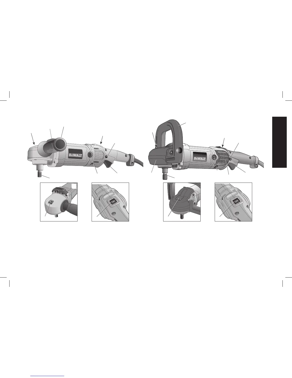
Auxiliary Handle (Fig. 1)
An auxiliary handle (F) is furnished with your tool and can be installed
on either side of the gear case. This handle should be used at all times
to maintain complete control of the tool.
A bale handle (H) is also provided with the DWP849X and can be used
in place of the auxiliary handle.
Variable Speed Trigger Switch (Fig. 1)
These tools are equipped with a variable speed trigger switch that
permits speed control from 0 to 3500 RPM. To turn the tool on,
squeeze the trigger switch (C) shown in Figure 1 until the tool starts
to run. The farther you depress the trigger, the faster it will operate.
Releasing the trigger turns the tool off.
FIG. 1
DWP849
B
F
D
C
G
A
E
I
B
E
DWP849X
C
H
E
I
D
G
A
K
J
E
AA