9
ENGLISH
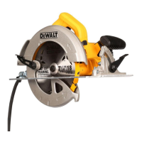
Description (Fig. A–C, F, G)
WARNING: Never modify the power tool or any part of it.
Damage or personal injury couldresult.
1
Plunge trigger
2
On/off switch
3
Main handle
4
Shoe
5
Bevel adjustment knob
6
Depth adjustment knobs
7
Depth scale
8
Front handle
9
Dust extraction outlet
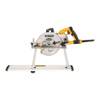
10
Rail adjuster
11
Blade
12
Lock button
13
Lock lever
14
Blade clamping screw
15
Outer flange
16
Inner flange
17
Riving knife
18
Riving knife adjustment screws
19
Speed wheel
20
Cutting indicator
21
Anti-kickback knob
22
Outer guard
23
Guide rail
24
Blade position indicators
25
Bevel scale
Intended Use
The DWS520 plunge saw is designed for professional sawing
applications and cutting wood products.
DO NOT use under wet conditions or in the presence of
flammable liquids orgases.
This heavy-duty plunge saw is a professional power tool.
DO NOT let children come into contact with the tool.
Supervision is required when inexperienced operators use
thistool.
• Young children and the infirm. This appliance is not
intended for use by young children or infirm persons
without supervision.
• This product is not intended for use by persons (including
children) suffering from diminished physical, sensory or
mental abilities; lack of experience, knowledge or skills
unless they are supervised by a person responsible for their
safety. Children should never be left alone with thisproduct.
ASSEMBLY AND ADJUSTMENTS
WARNING: To reduce the risk of serious personal
injury, turn tool off and disconnect tool from power
source before making any adjustments or removing/
installing attachments or accessories. Be sure the
trigger switch is in the OFF position. An accidental start-up
can cause injury.
Bevel Adjustment (Fig. A)
The bevel angle can be adjusted between 0° and 47°.
1. Loosen the bevel adjustment knobs
5
.
2. Set the bevel angle by tilting the saw shoe
4
until the mark
indicates the desired angle on the bevel scale
25
.
3. Tighten the bevel adjustment knobs
5
.
Changing the Saw Blade (Fig. A–C)
1. Press the lock button
12
.
2. Press the plunge saw down to stop (blade change position).
3. Turn the lock lever
13
clockwise until it stops.
4. Press the lock lever
13
down and rotate the blade until the
lock position is found.
NOTE: The blade
11
is now locked and cannot be turned
byhand.
5. Turn the blade clamping screw
14
anti-clockwise
toremove.
6. Remove the outer flange
15
and used blade
11
. Place the
new blade on the inner flange
16
.
7. Replace the outer flange
15
and blade clamping screw
14
.
Turn the screw clockwise by hand.
NOTE: The direction of rotation of the saw blade and the
rotation of the plunge saw MUST be the same.
8. Tighten the blade clamping screw firmly using the hex key.
9. Release and turn the lock lever
13
anti-clockwise until
itstops.
10. Move the plunge saw back to top position.
11. Push plunge trigger
1
forward, to lock saw blade change.
Adjusting the Riving Knife (Fig. A–C)
For the correct adjustment of the riving knife
17
, refer to the
figureC. Adjust the clearance of the riving knife after changing
the saw blade or whenever necessary.
1. Follow Changing the Saw Blade steps 1–4.
2. Loosen the riving adjustment screw
18
with an hex key and
set the riving knife as shown in figureC.
3. Tighten the riving knife screw
18
.
4. Turn the lock lever
13
anti-clockwise until it stops.
5. Move the plunge saw back to top position.
6. Push plunge trigger
1
forward, to lock saw blade change.
Depth of Cut Adjustment (Fig. D)
The cutting depth can be set at 0–59 mm without guide rail
attached; with the guide rail attached: 0–55 mm.
1. Loosen the depth adjustment knob
6
and move the
pointer to obtain the correct depth of cut.
2. Tighten the depth adjustment knob
6
.
NOTE: For optimal results, allow the saw blade to protrude from
the workpiece by about 3 mm (Fig.D).

 Loading...