10
ENGLISH
The plywood must sit flush on the work support. When clamping the
saw to any work surface, clamp only on the clamping bosses where
the mounting screw holes are located. Clamping at any other point will
interfere with the proper operation of thesaw.
3. To prevent binding and inaccuracy, be sure the mounting surface is
not warped or otherwise uneven. If the saw rocks on the surface, place
a thin piece of material under one saw foot until the saw is firm on the
mountingsurface.
Assembling the Base Extensions (Fig. V)
WARNING: Base extensions must be assembled to both sides of
the saw's base before using thesaw.
WARNING: Be sure to adjust the base extensions using the
mounting slots so they are level with the saw'sbase.
1. Locate the holes above the hand indentations on the side of thebase.
2. Using a hex wrench, attach the screw
46
through the nut
47
, through
the base extension
30
, and into the holes on thebase.
3. Ensure the extension is secure by pulling on the extension to verify
nomovement.
4. Repeat steps 1 through 3 on the otherside.
NOTE: Make sure the extensions are level with the work surface so that the
workpiece rests evenly. A straight workpiece should have no gap between it
and the baseextensions.
Changing or Installing a New Saw Blade (Fig. A, C–E)
WARNING: To reduce the risk of injury, wear gloves when handling
the sawblade.
WARNING: To reduce the risk of injury, turn unit off and
disconnect machine from power source before installing and
removing accessories, before adjusting or changing set-ups
or when making repairs. Be sure the trigger switch is in the OFF
position. An accidental start-up can causeinjury.
• Never depress the spindle lock button while the blade is under
power orcoasting.
• Do not cut light alloy and ferrous metal (containing iron or steel)
or masonry or fibre cement product with this mitresaw.
Removing the Blade
1. Unplug thesaw.
2. Insert the 6mm hex key
24
into the opposite location of the blade
shaft and hold it(Fig.D).
3. Loosen the blade bolt
5
by turning clockwise. Remove the blade bolt
and the outer flange
4
.
4. Press the lower guard lock release lever
2
to raise the lower blade
guard
6
and remove the saw blade
7
.
Installing a Blade
1. Unplug thesaw.
2. Install the new saw blade onto the shoulder provided on the inner
flange
33
making sure that the teeth at the bottom edge of the blade
are pointing towards the fence (away from the operator).
3. Replace the outer flange
4
, making sure that the location lugs
34
are
engaged correctly, one on each side of the motorshaft.
4. Tighten the blade bolt
5
by turning counterclockwise while holding
the 6mm hex key
24
engaged with your other hand (Fig.D).
WARNING: Be aware the saw blade shall be replaced in the described
way only. Only use saw blades as specified under Technical Data;
Cat. no.: DT4320 issuggested.
Transporting the Saw (Fig. A, B)
WARNING: To reduce the risk of serious personal injury,
ALWAYS lock the rail lock knob, mitre latch, bevel clamp handle, lock
down button and fence lock knobs before transporting the saw. Never
use guards for transporting or liftingup.
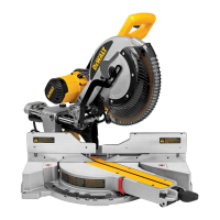
5
Blade bolt
6
Lower blade guard
7
Saw blade
8
Sliding fence lock knob
9
Fixed table
10
Kerf plate
11
Mitre arm
12
Mitre latch
13
Rotating table
14
Mitre scale
15
Sliding fence
16
Material clamp
17
Rail lock knob
18
Bevel clamp handle
19
Bevel scale
20
Bench mounting holes
21
Lock down button
22
Rails
23
Saw head
24
Hex keys (Fig. C)
25
Cable clamp
26
Cable
27
Speed control dial
(DWS771only)
28
Padlock hole
29
Bevel override lever
30
Base extension handles
31
Dust extraction port
32
Date code
Intended Use
Your
cross-cut mitre saw has been designed for professional
cutting wood, wood products and plastics. When using the appropriate
saw blades, sawing aluminium is also possible. It performs the sawing
operations of cross-cutting, bevelling and mitring easily, accurately
andsafely.
This unit is designed for use with a nominal blade diameter 216mm carbide
tipblade.
DO NOT use under wet conditions or in the presence of flammable liquids
orgases.
These miter saws are professional powertools.
DO NOT let children come into contact with the tool. Supervision is
required when inexperienced operators use thistool.
WARNING! Do not use the machine for purposes other thanintended.
• Young children and the infirm. This appliance is not intended for use
by young children or infirm persons withoutsupervision.
• This product is not intended for use by persons (including children)
suffering from diminished physical, sensory or mental abilities; lack of
experience, knowledge or skills unless they are supervised by a person
responsible for their safety. Children should never be left alone with
thisproduct.
ASSEMBLY
WARNING: To reduce the risk of serious personal injury, turn
tool off and disconnect tool from power source before making
any adjustments or removing/installing attachments or
accessories. Be sure the trigger switch is in the OFF position. An
accidental start-up can causeinjury.
Unpacking
The motor and guards are already assembled onto thebase.
Cable Clamp (Fig. C)
Verify the cable
26
runs through the cable clamp
25
. Allow enough cable
for the saw head to travel, then tighten the clamp by means of thescrew.
Bench Mounting (Fig. B)
1. Holes
20
are provided in all four feet to facilitate bench mounting.
Two different sized holes are provided to accommodate different sizes
of bolts. Use either hole; it is not necessary to use both. Bolts with a
diameter of 8mm and 80mm in length is suggested. Always mount
your saw firmly to prevent movement. To enhance the portability, the
tool can be mounted to a piece of 12.5mm or thicker plywood which
can then be clamped to your work support or moved to other job sites
andreclamped.
2. When mounting your saw to a piece of plywood, make sure that the
mounting screws do not protrude from the bottom of the wood.
 Loading...