13
ENGLISH
1. Loosen the bevel clamp handle
18
by pulling it outward then down
and set the bevel asdesired.
2. Set the override lever
29
ifrequired.
3. Hold the head firmly and do not allow it tofall.
4. Tighten the bevel clamp handle
18
firmly.
5. Proceed as for a vertical straight cross-cut.
Quality of Cut
The smoothness of any cut depends on a number of variables, i.e. the
material being cut. When smoothest cuts are desired for moulding andother
precision work, a sharp (60-tooth carbide) blade and a slower, even cutting
rate will produce the desiredresults.
WARNING: Ensure that the material does not creep while cutting;
clamp it securely in place. Always let the blade come to a full stop
before raising the arm. If small fibres of wood still split out at the rear
of the workpiece, stick a piece of masking tape on the wood where
the cut will be made. Saw through the tape and carefully remove tape
whenfinished.
Clamping the Workpiece (Fig. R)
WARNING: A workpiece that is clamped, balanced and secure
before a cut may become unbalanced after a cut is completed. An
unbalanced load may tip the saw or anything the saw is attached to,
such as a table or workbench. When making a cut that may become
unbalanced, properly support the workpiece and ensure the saw is
firmly bolted to a stable surface. Personal injury mayoccur.
WARNING: The clamp foot must remain clamped above the base of
the saw whenever the clamp is used. Always clamp the workpiece to
the base of the saw – not to any other part of the work area. Ensure
the clamp foot is not clamped on the edge of the base of thesaw.
CAUTION: Always use a work clamp to maintain control and reduce
the risk of personal injury and workpiecedamage.
For best results use the material clamp
16
made for use with yoursaw.
To Install Clamp
1. Insert it into the hole behind the fence. The clamp
16
should be facing
toward the back of the mitre saw. Ensure the groove on the clamp rod is
fully inserted into the base of the mitre saw. If the groove is visible, the
clamp will not besecure.
2. Rotate the clamp 180º toward the front of the mitresaw.
3. Loosen the knob to adjust the clamp up or down, then use the fine
adjust knob to firmly clamp theworkpiece.
NOTE: Place the clamp on the right side of the base when beveling.
ALWAYS MAKE DRY RUNS (UNPOWERED) BEFORE FINISH CUTS TO CHECK
THE PATH OF THE BLADE. ENSURE THE CLAMP DOES NOT INTERFERE
WITH THE ACTION OF THE SAW ORGUARDS.
Compound Mitre (Fig. S, T)
This cut is a combination of a mitre and a bevel cut. This is the type of cut
used to make frames or boxes with slanting sides like the one shown in
FigureS.
WARNING: If the cutting angle varies from cut to cut, check that
the bevel clamp handle and the mitre clamping knob are securely
tightened. These must be tightened after making any changes in bevel
ormitre.
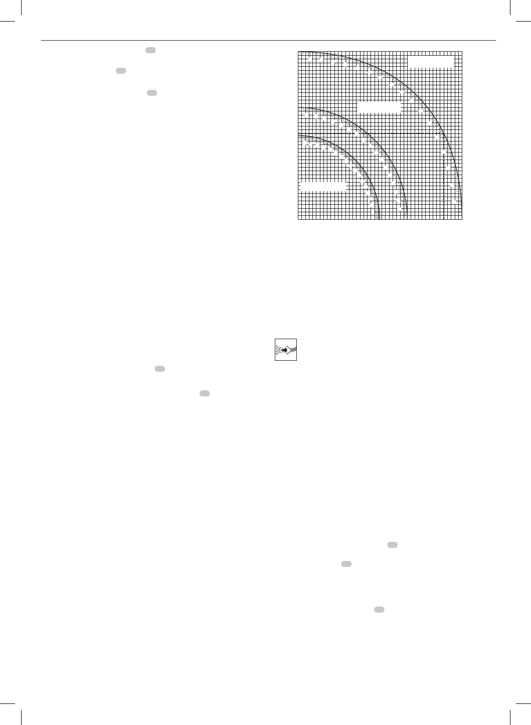
• The chart shown below will assist you in selecting the proper bevel and
mitre settings for common compound mitrecuts.
• To use the chart, select the desired angle “A” (Fig.T) of your project and
locate that angle on the appropriate arc in the chart. From that point
follow the chart straight down to find the correct bevel angle and
straight across to find the correct mitreangle.
0510 15 20 25 30 35 40 45
0510 15 20 25 30 35 40 45
5
10
15
20
25
30
35
40
45
5
10
15
20
25
30
35
40
5
10
15
20
25
30
35
40
45
50
55
60
65
70
75
80
85
5
10
15
20
25
30
35
40
45
50
55
60
65
70
75
80
85
5
10
15
20
25
30
35
40
45
50
55
60
65
70
75
80
85
SET THIS BEVEL ANGLE ON SAW
SET THIS MITER ANGLE ON SAW
ANGLE OF SIDE OF BOX (ANGLE"A")
SQUARE BOX
6 SIDED BOX
8 SIDED BOX
1. Set your saw to the prescribed angles and make a few trialcuts.
2. Practice fitting the cut piecestogether.
Example: To make a four-sided box with 25° exterior angles (angle “A”)
(Fig.T), use the upper right arc. Find 25° on the arc scale. Follow the
horizontal intersecting line to either side to get the mitre angle setting
on the saw (23°). Likewise follow the vertical intersecting line to the top
or bottom to get the bevel angle setting on the saw (40°). Always try
cuts on a few scrap pieces of wood to verify the settings on thesaw.
WARNING: Never exceed the compound mitre limits of 45° bevel with
45° left or rightmitre.
Dust Extraction (Fig. A, U)
WARNING: To reduce the risk of serious personal injury, turn
tool off and disconnect tool from power source before making
any adjustments or removing/installing attachments or
accessories. An accidental start-up can causeinjury.
WARNING: Certain dust, such as oak or beech dust, is considered
carcinogenic, especially in connection with wood-treatmentadditives.
• Always use dustextraction.
• Provide for good ventilation of the workspace.
• It is recommended to wear an appropriaterespirator.
CAUTION: Never operate this saw unless the dust bag or
dust extractor is in place. Wood dust may create a
breathinghazard.
CAUTION: Check and clean the dust bag each time afterusing.
WARNING: When sawing aluminium, remove the dust bag, or
disconnect the dust extractor to avoid the risk offire.
Your mitre saw has a built-in dust port
31
that allows connection to
either a dust bag (33mm nozzles) or direct attachment to the
AirLock(DWV9000-XJ)
45
.
Observe the relevant regulations in your country for the materials to
beworked.
To Attach the Dust Bag
1. Fit a dust bag to the dust port
31
.
To Empty the Dust Bag
1. Remove dust bag from the saw and gently shake or tap the dust bag
toempty.
2. Reattach the dust bag back onto the dustport.
You may notice that all the dust will not come free from the bag. This will
not affect cutting performance but will reduce the saw's dust collection
 Loading...