37
ENGLISH
Keep hands 100 mm from either side of saw blade.
Do not stare directly into the light source.
Carryingpoint.
Date Code Position (Fig. A1)
The date code
6
, which also includes the year of manufacture, is printed
into thehousing.
Example:
2019 XX XX
Year of Manufacture
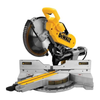
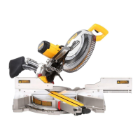
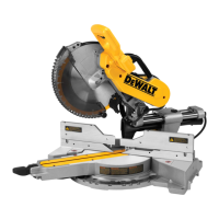
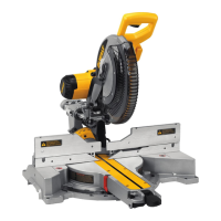
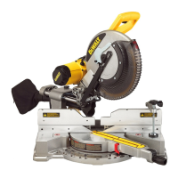
Description (Fig. A1–E)
WARNING: Never modify the power tool or any part of it. Damage or
personal injury couldresult.
Fig. A1
1
Lower guard
2
Operating handle
3
Carrying handle
4
Rail lock knob
5
Rail set screw adjustment
6
Date code
7
Rails
8
Bevel scale
9
Lock down pin
10
Fence adjustment knob
11
Fence
12
Base fence
13
Base extension handles
14
Hand indentation
15
Table
16
Bench mounting holes
17
Mitre scale
18
Dust duct inlet
19
Mitre lock handle
20
Mitre latch button
21
Kerf plate
Fig. A2
22
Trigger switch
23
Lock-off lever
24
Padlock hole
25
XPS on/off switch
26
Wing nut
27
Depth adjustment screw
28
Grooving stop
29
Blade wrench
30
Base
31
Bevel lock knob
32
0° bevel stop override
33
Dust extraction port
34
Belt cover
35
Electronic speed control dial
36
Fence lanyard
37
Workpiece clamp (Fig. B)
Optional accessories
Fig. C
38
DW7053-XJ Dustbag
Fig. D
39
DE7023-XJ / DE7033-XJ Leg stand
Fig. E
40
DE7025-XJ Clamp brackets
Intended Use
Your
DWS780 mitre saw has been designed for professional
cutting of wood, wood products and plastics. When using the appropriate
saw blades, sawing aluminium is also possible. It performs the sawing
operations of cross-cutting, bevelling and mitring easily, accurately
andsafely.
This unit is designed for use with a nominal blade diameter 305 mm carbide
tipblade.
DO NOT use under wet conditions or in the presence of flammable liquids
orgases.
These mitre saws are professional powertools.
DO NOT let children come into contact with the tool. Supervision is
required when inexperienced operators use thistool.
WARNING: Do not use the machine for purposes other thanintended.
• This product is not intended for use by persons (including children)
suffering from diminished physical, sensory or mental abilities; lack of
experience, knowledge or skills unless they are supervised by a person
responsible for their safety. Children should never be left alone with
thisproduct.
ASSEMBLY AND ADJUSTMENTS
WARNING: To reduce the risk of injury, turn unit off and
disconnect machine from power source before installing and
removing accessories, before adjusting or changing set-ups
or when making repairs. Be sure the trigger switch is in the OFF
position. An accidental start-up can causeinjury.
Unpacking (Fig. A1, F)
1. Open the box and lift the saw out by the con venient carrying handle
3
,
as shown in FigureF.
2. Place the saw on a smooth, flatsurface.
3. Release the rail lock knob
4
, and push the saw head back to lock it in
the rearposition.
4. Press down lightly on the operating handle
2
and pull out the lock
down pin
9
.
5. Gently release the downward pressure and hold the operating handle,
allowing it to rise to its fullheight.
Bench Mounting (Fig. A1)
Holes
16
are provided in all four feet to facilitate bench mounting. Two
different-sized holes are provided to accommodate different sizes of screws.
Use either hole; it is not necessary to useboth.
Always mount your saw firmly to a stable surface to prevent movement.
To enhance the tool’s portability, it can be mounted to a piece of 12.7 mm
or thicker plywood which can then be clamped to your work support or
moved to other job sites andreclamped.
NOTE: If you elect to mount your saw to a piece of plywood, make sure that
the mounting screws don’t protrude from the bottom of the wood. The
plywood must sit flush on the work support. When clamping the saw to
any work surface, clamp only on the clamping bosses where the mounting
screw holes are located. Clamping at any other point will interfere with the
proper operation of thesaw.
CAUTION: To prevent binding and inaccuracy, be sure the mounting
surface is not warped or otherwise uneven. If the saw rocks on the
surface, place a thin piece of material under one saw foot until the saw
sits firmly on the mountingsurface.
Kerf Plate Replacement (Fig. A1)
To remove the kerf plate
21
, remove the screws holding the kerf plate in
place and replace with a new one.
Assemble the screws back in by following this sequence: first through the
round holes located halfway from the ends, then through the slots at the
ends. No adjustment is necessary.
Assembling the Base Extensions (Fig. Y)
WARNING: Base extensions must be assembled to both sides of
the saw's base before using thesaw.
WARNING: Be sure to adjust the base extensions using the
mounting slots so they are level with the saw'sbase.
1. Locate the holes above the hand indentations
14
on the side of
thebase.
2. Using a hex wrench, attach the screw
60
through the washer
61
,
through the base extension
13
, and into the holes on thebase.
3. Ensure the extension is secure by pulling on the extension to verify
nomovement.
4. Repeat steps 1 through 3 on the otherside.
NOTE: Make sure the extensions are level with the work surface so that the
workpiece rests evenly. A straight workpiece should have no gap between it
and the base extensions.
Changing or Installing a New Saw Blade
Removing the Blade (Fig. G1–G4)
WARNING: To reduce the risk of injury, wear gloves when handling
the sawblade.
 Loading...