16 17
In any of these cases, the LCD screen will continuously display the
following:
The USB Icon and the Fault Icon will flash. The USB Port will
automatically shut down. Should this occur:
a. Disconnect the USB-powered device and press the USB Power
Button again to turn off the USB Port immediately.
b. Allow the unit to cool down for several minutes before attempting
to use the USB Port again.
c. If a fault occurs again, make sure that the draw of the USB
device plugged into the USB Port does not exceed 3.1A.
d. If an individual USB device is within specifications and the fault
occurs, have the USB device checked for malfunction and do
not continue to use it with this USB Port.
3. Some household USB-powered electronics will not operate with
this unit.
USING THE USB PORT
1. Plug the battery charger’s AC Power Cord into a functioning
AC outlet. A beep will sound and the LCD Screen will show the
following:
The (empty) Battery Icon will light solid to indicate the built-in
Battery Clamps are not yet connected to the battery.
2. Press the USB Power Button to turn on the USB Port. A beep will
sound, the USB Power/Fault Indicator around the USB Port will light
blue and the LCD Screen will continuously display the following:
The USB Icon will light solid, indicating the USB port is ready to use.
3. Plug the USB-powered device into the USB power port and operate
normally.
4. Press the USB power button again to turn off the USB Port.
AC Pass Through
This unit features a 120V AC Pass Through. When using this feature,
follow all instructions and warnings found in the “Specific Safety
Instructions for the AC Pass Through” in the front of this Instruction
Manual.
NOTE: The 120V AC Pass Through is protected by a fuse located
on the back of the unit (see Fig. 2). If the 120V AC Pass Through
shuts down when it is in use, this fuse may have blown. Refer to the
“Maintenance” and “Troubleshooting” sections for more information.
Care and Maintenance
WARNING: To reduce the risk of electric shock, unplug the battery
charger from the outlet before attempting any maintenance or cleaning.
Turning off the controls will not reduce this risk.
Starting the Engine
1. Refer to the “Charging the Battery” section of this Instruction
Manual. Set up the battery charger and connect to the battery
following steps 1 and 2. The unit will be in Standby Mode.
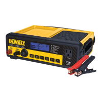
2. Press the Engine Start Button once. A beep will sound and the
LCD Screen shows the following:
The Digital Display shows the countdown from “60” to “0” to
indicate the unit is in Engine Start Mode. The bars on the Battery
Icon will change from empty to solid (bottom to top) repeatedly.
The Clamp Icons and the Battery Icon will light solid.
NOTES:
A. The Engine Start function may not be started if the battery
charger detects that the battery is at full capacity (fully
charged).
B. The Engine Start countdown process can be terminated by
pressing the Engine Start Button again to stop the function.
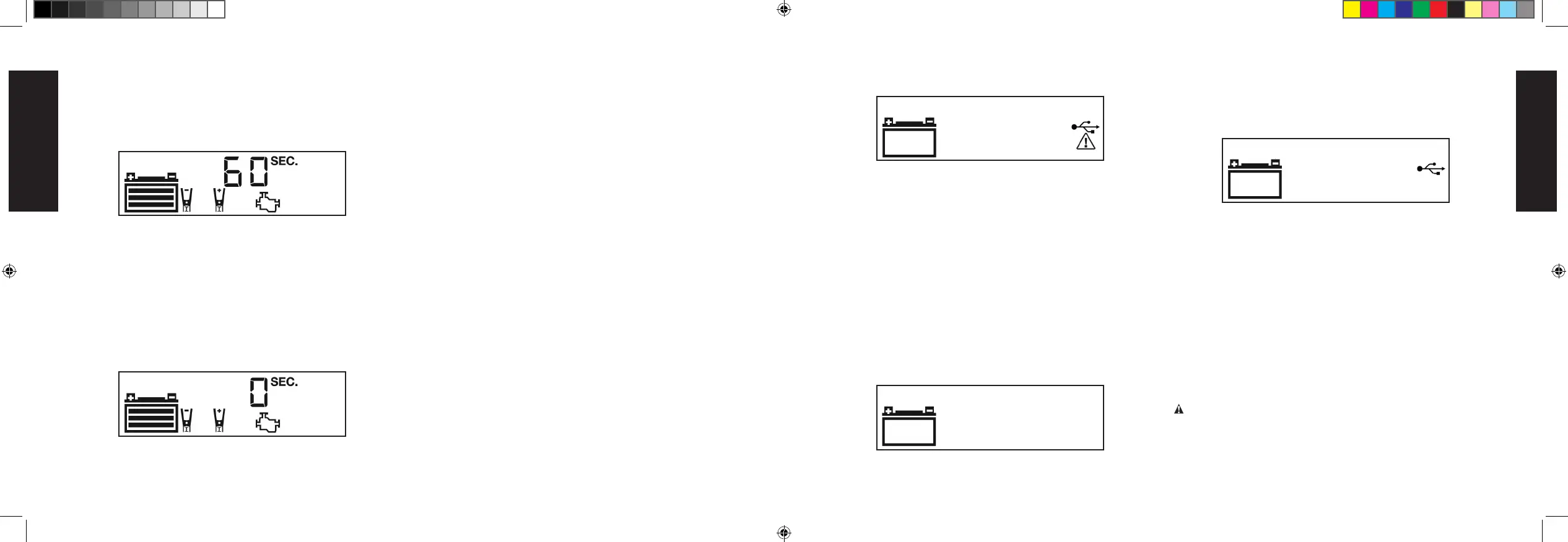
3. When “0” is reached, a beep will sound and the LCD Screen will
show the following:
The Pump Engine Icon will light solid and the Digital Display
shows “0 SEC” to indicate the vehicle is ready to start. The
Clamps Icon and the Battery Icon light solid.
4. Crank the engine using manufacturer’s guidelines, typically in 3 to
5 second bursts. The Digital Display shows “5 SEC” (a 5-second
countdown to use as a timer when cranking the engine).
5. After cranking, the unit will automatically adjust the charging current
to 7.5A for 5 minutes, and then revert to Charging Mode. To stop
charging, press the Battery Charge Button.
IMPORTANT: The Engine Start function requires a resting/cooling
period between attempts. Wait 4 to 5 minutes before a second
attempt at starting the engine, if needed.
6. When disconnecting the battery charger, unplug the AC Power
Cord, and then disconnect the battery charger from the battery
following the last step of the directions in the “Preparing to Charge”
section of this Instruction Manual.
USB Port
The USB Power Button and the USB Port are located on the front of
unit. The USB Power/Fault Indicator is a translucent ring around the
USB Port. Refer to Fig. 1 to locate.
Important Notes Concerning the USB Port
1. This unit’s USB Port does not support data communication. It only
provides power to an external USB-powered device. The USB Port
provides up to 3.1A (5V).
2. When the USB Port is in use, the unit will monitor for the following
USB fault conditions: thermal fault, overload and short circuit. If a
fault condition exists the USB Power/Fault Indicator will flash blue.
DXAEC801B_DXAEC801BCA_ManualENFRSP_080320.indd 16-17 10:30 AM
English
11/04/20