Do you have a question about the DeWalt DXCMV5048055 and is the answer not in the manual?
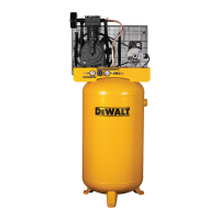
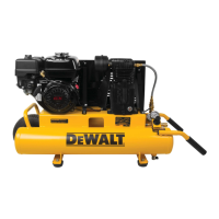
Identifies and labels the key components of the air compressor unit.
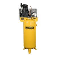
Details the technical specifications for the pump and the overall air compressor unit.
Explains the severity levels for DANGER, WARNING, and CAUTION signal words.
Details risks related to flammable vapors, ventilation, and air inhalation.
Covers dangers of air tank integrity, safe accessory use, and tire inflation.
Provides guidance on safe handling, storage, and hazards from compressed air streams.
Alerts to burns from hot parts and risks of electric shock.
Emphasizes safe practices and warns about entanglement with moving components.
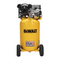
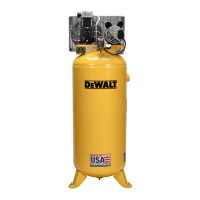
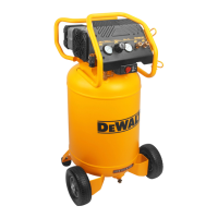
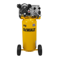
Introduces the unit's main features, controls, and basic components.
Describes the function of parts like filters, gauges, regulator, and pump.
Covers unpacking, inspection, and connecting hoses to the compressor.
Guides on choosing a suitable location and securely anchoring the compressor.
Provides essential guidelines for safe and correct electrical wiring.
Details requirements for electrical supply, protection, and grounding.
Offers advice on setting up the air distribution system, including a diagram.
Explains the process of starting the compressor and adjusting pressure.
Details stopping the compressor and draining the tank correctly.
Presents a schedule for daily, weekly, monthly, and annual maintenance.
Provides instructions on how to test the safety valve for proper function.
Guides on inspecting, cleaning, or replacing the air filter element.
Explains the procedure for draining condensation from the air tank.
Details how to check the oil level and perform an oil change.
Outlines the steps for safely replacing the compressor's drive belt.
Describes how to set the correct belt tension for optimal performance.
Explains how to align pulleys for proper belt tracking and wear.
Provides steps to check for and correct air leaks in the system.
Covers torquing head bolts and servicing the check valve.
Information on obtaining further service and recommended accessories.
Outlines the terms, coverage, and duration of the product warranty.
Lists items and conditions excluded from warranty coverage.
Provides instructions on getting service and understanding warranty rights.
Lists common problems, their potential causes, and corrective actions.
Provides a code-based guide for diagnosing and resolving specific issues.
Defines key terms and abbreviations used throughout the manual for clarity.
This document is an instruction manual for the DEWALT DXCMV5048055 Two Stage, Belt Drive, Electric Air Compressor. It provides comprehensive information on the compressor's features, installation, operation, maintenance, and safety guidelines.
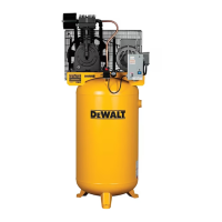
The DEWALT DXCMV5048055 is an oil-lubricated, two-cylinder, two-stage, belt-driven electric air compressor designed to compress air into an air tank for various applications. The compressed air is then available at the air outlet for use with air tools and accessories.
The air compressor operates by drawing in ambient air through an air intake filter, compressing it in two stages using a two-cylinder pump, and then storing the compressed air in an air tank. The motor, controlled by a pressure switch, automatically starts when the air tank pressure drops below a factory-set cut-in pressure and stops when it reaches the cut-out pressure. A safety valve is incorporated to prevent system failures by relieving pressure if it exceeds a predetermined level. A check valve allows compressed air to enter the air tank when the compressor is operating and closes to retain pressure when the compressor stops. The air pressure available at the outlet is regulated by a pressure regulator, which can be adjusted to suit the requirements of different air tools and accessories. An air tank drain valve at the base of the tank allows for the removal of condensed water. The motor is equipped with a thermal overload protector that shuts off the motor if it overheats, requiring a cool-down period before restarting.
To start the compressor, the Auto/Off switch (B) is set to "Auto," allowing the tank pressure to build until the motor stops at the cut-out pressure. The regulator knob (E) is then pulled out and turned clockwise to increase the outlet pressure to the desired level, after which it is pushed in to lock. When using the compressor, it's crucial to refer to the manufacturer's instructions for any attached air tools or accessories. The compressor should always be operated in a clean, dry, and well-ventilated area, at least 12 inches (30.5 cm) away from walls or obstructions to ensure proper airflow. It is recommended to locate the compressor as close as possible to the main power supply to avoid power loss due to long electrical wiring. For air distribution systems, metal piping is recommended, and a flexible coupling should be installed between the globe valve/air discharge outlet and the main air distribution line to absorb vibration. A separate regulator is advised for controlling air pressure for individual air-driven tools, as tank pressure is often too high. Lubricators should not be installed between the tank and spray equipment or oil-free air tools.
To stop the compressor, the Auto/Off switch is set to "Off." The regulator knob is pulled out and turned counterclockwise to fully close, ensuring the regulated pressure gauge reads 0 psi, then pushed in to lock. The air hose and any accessories should be removed, and the air tank must be drained daily to prevent corrosion and weakening of the tank. After draining, the drain valve is closed, and the compressor is allowed to cool down before being wiped clean and stored in a safe, non-freezing area.
Routine maintenance is essential for efficient operation and extended life of the air compressor. A maintenance schedule is provided, including daily, weekly, monthly, and yearly checks. Daily tasks include checking the safety valve, draining the air tank, and inspecting the pump oil level. The air filter (A) must be kept clean and free of obstructions to ensure a clean, cool, and dry air supply to the pump. The pump oil level should be maintained at the middle of the sight glass (S), and only synthetic blend non-detergent air compressor oil should be used. Oil changes are recommended after the first 20 hours of operation, and then every 200 hours or once a year, whichever comes first. Overfilling with oil can lead to premature compressor failure.
The drive belt tension should be checked regularly; it should deflect 1/2 inch (13 mm) midway between the pulley and flywheel with a 10-pound (4.6 kg) weight applied. The motor pulley and flywheel must be aligned within 1/16 inch (1.6 mm) to prevent excessive belt wear. Air lines and fittings should be inspected for leaks using a soap solution, and any leaks found must be corrected to prevent the compressor from overworking. The air compressor pump head bolts should be torqued to 14-16 ft.-lbs. (18.9–21.7 Nm) after the first five hours of operation.
All maintenance and repair operations not listed in the manual should be performed by a trained service technician or an authorized DEWALT service center. Before any maintenance or repair, the compressor must be turned off, disconnected from the power source, and all air pressure bled from the system. Hot surfaces, moving parts, and electrical shock hazards must be avoided during maintenance. If warning labels become illegible or are missing, free replacements can be obtained.
| Quantity per pack | 1 pc(s) |
|---|