35
ENGLISH
Keep bystandersaway.
Directive 2000/14/EC guaranteed
soundpower.
Date Code Position (Fig. U)
The date code
45
, which also includes the year of manufacture,
is printed into thehousing.
Example:
2017 XX XX
Year of Manufacture
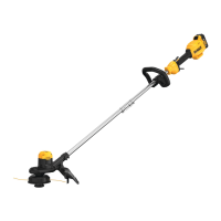
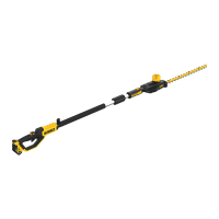
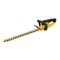
Description (Fig. A)
WARNING: Never modify the power tool or any part of it.
Damage or personal injury couldresult.
1
Variable speed trigger
2
Lock-off lever
3
Lock-off tab
4
Handle
5
Speed control switch
6
Auxiliary handle
7
Motor housing
8
Trimmer pole
9
Strap mount
10
Strap
11
Guard
12
Spool housing
13
Battery housing
14
Battery pack
15
Battery release button
16
Brush cutter blade
17
Nut wrench
18
Blade cover
Intended Use
Your string trimmer / brush cutter has been designed for
professional trimmingapplications.
DO NOT use under wet conditions or in the presence of
flammable liquids orgases.
DO NOT let children come into contact with the tool.
Supervision is required when inexperienced operators use
thistool.
• Young children and the infirm. This appliance is not
intended for use by young children or infirm persons
without supervision.
• This product is not intended for use by persons (including
children) suffering from diminished physical, sensory or
mental abilities; lack of experience, knowledge or skills
unless they are supervised by a person responsible for their
safety. Children should never be left alone with thisproduct.
ASSEMBLY AND ADJUSTMENTS
WARNING: To reduce the risk of serious personal
injury, turn tool off and disconnect battery pack
before making any adjustments or removing/
installing attachments or accessories. An accidental
start-up can causeinjury.
WARNING: Use only
battery packs andchargers.
Inserting and Removing the Battery Pack
from the Tool (Fig. C–E)
NOTE: Make sure your battery pack
14
is fullycharged.
To Install the Battery Pack into the Tool
1. Align the battery pack
14
with the rails inside the tool
(Fig.C).
2. Slide it into the tool until the battery pack is firmly seated
and ensure that you hear the lock snap intoplace.
To Remove the Battery Pack from the Tool
1. Press the release button
15
and firmly pull the battery pack
out of the toolhandle (Fig. D).
2. Insert battery pack into the charger as described in the
charger section of thismanual.
Fuel Gauge Battery Packs (Fig. E)
Some
battery packs include a fuel gauge which
consists of three green LED lights that indicate the level of
charge remaining in the batterypack.
To actuate the fuel gauge, press and hold the fuel gauge button
19
. A combination of the three green LED lights will illuminate
designating the level of charge left. When the level of charge
in the battery is below the usable limit, the fuel gauge will not
illuminate and the battery will need to berecharged.
NOTE: The fuel gauge is only an indication of the charge left on
the battery pack. It does not indicate tool functionality and is
subject to variation based on product components, temperature
and end-userapplication.
Assembly
Removing spool housing (Fig. A, F, G)
1. Insert the rod
46
through the hole
21
in the string trimmer
drive washer (small)
20
and into the hole
22
in the motor
housing
7
as shown in figureF.
2. Turn the spool housing
12
clockwise as shown in figureG.
3. Remove the spool housing and the drive washer from
thetrimmer.
Attaching guard (Fig. A, H, I)
WARNING: Never operate appliance without guard firmly
in place. Damage or personal injury couldresult.
1. Remove the spool housing
12
as described in the
Removing the spool housingsection.
2. To attached the guard, slide the tab
23
of the guard under
the lip
24
of the motor housing
7
, then lower the back of
the guard into place as shown in figureH.

 Loading...