36
ENGLISH
3. Replace and securely tighten the 4 guard screws
25
with
the wrench
17
as shown in figureI.
4. Replace the spool housing as described in the Attaching
Spool Housing sectionbelow.
Attaching spool housing (Fig A, I, J)
1. Slide the string trimmer drive washer (small)
20
down over
the the bolt
26
protruding from the trimmer so that its hole
21
lines up with the hole
22
in the motor housing
7
.
2. Rotate the washer and motor housing until their holes line
up with the notch
27
in the guard
11
.
3. Insert a screwdriver through the three holes, thread the
spool housing counterclockwise, and securely tighten onto
thebolt.
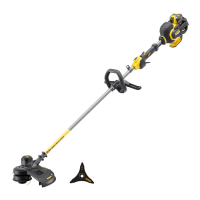
Attaching blade (Fig. A, K)
WARNING: Risk of injury. Brush cutter blade has sharp
edges. Wear gloves when handlingblade.
1. Remove the spool housing
12
and the string trimmer drive
washer (small)
20
as described in the Removing the spool
housingsection.
2. Slide the brush cutter drive washer (large)
28
down over
the the bolt
26
protruding from the trimmer so that its hole
29
lines up with the hole
22
in the motor housing
7
.
3. Slide the brush cutter blade
16
on top of drive washer
so that the inner, non-cutting edge
30
lines up with the
hole of the drive washer. This will allow for easier and safer
removal of the bladelater.
4. Slide the brush cutter clamp washer
31
on top of the blade
so that the wider side is flat against theblade.
5. Screw the brush cutter nut
32
onto the bolt with the
wrench
17
. Ensure the nut is securelytightened.
6. Slide the cotter pin
33
fully through the hole in thebolt.
Attaching auxiliary handle (Fig. A, L)
1. Place the auxiliary handle
6
onto the top of the trimmer
pole
8
above the label placed in the middle fo thepole.
2. Slide the bracket
34
of the auxiliary handle into the bottom
of thehandle.
3. Thread the handle bolts
35
through the bracket and into
thehandle.
4. Tighten the handle bolts with the wrench
17
. Ensure the
handle is securelyattached.
If adjustment is necessary, loosen the handle bolts and slide the
auxiliary handle up or down the trimmer pole. Then, retighten
thebolts.
Replacing guard (Fig. I, M)
1. Remove the spool housing
12
as described in the
Removing the spool housingsection.
2. Remove the 4 guard screws
25
shown in figureI.
3. Lift the guard off at an angle as shown in figureM.
4. Install the new guard as described in the Attaching
guardsection.
Attaching strap (Fig. A)
Hook the strap
10
to the strap mount
9
and place strap on
one shoulder for extra support while using the trimmer or
brushcutter.
OPERATION
Instructions for Use
WARNING: Always observe the safety instructions and
applicableregulations.
WARNING: To reduce the risk of serious personal
injury, turn tool off and disconnect battery pack
before making any adjustments or removing/
installing attachments or accessories. An accidental
start-up can causeinjury.
Proper Hand Position (Fig.A,O)
WARNING: To reduce the risk of serious personal injury,
ALWAYS use proper hand position asshown.
WARNING: To reduce the risk of serious personal
injury, ALWAYS hold securely in anticipation of a
suddenreaction.
Proper hand position requires one hand on the handle
4
, with
the other hand on the auxiliary handle
6
.
Switching On (Fig. A)
To turn the appliance on, push the lock off tab
3
forward,
squeeze the lock-off lever
2
, and then squeeze the variable
speed trigger
1
.
To turn the appliance off, release the variable speed trigger, the
lock-off lever, andtab.
Speed Control Switch (Fig. A)
This string trimmer gives you the choice to operate at a
more efficient speed to extend the runtime for larger jobs, or
accelerate the trimmer speed for high-performance cutting.
To extend runtime, push the speed control switch
5
forward
toward the auxiliary handle
6
into the "LO" position. This mode
is best for larger projects that require more time tocomplete.
To accelerate the trimmer, pull the speed control switch back
toward the battery housing
13
into the "HI" position. This mode
is best to cut through heavier growth and for applications that
need higherRPM.
NOTE: When in "HI" mode, runtime will be decreased as
compared to when trimmer is in "LO"mode.
Trimming / Brush cutting (Fig. A, N, O)
With the trimmer on, angle it and swing side to side as shown
in figureN.
Maintain a minimum distance of 610 mm between the guard
and your feet as shown in figureO.
WARNING: Keep the rotating string roughly parallel with
the ground (tilted no more than 30 degrees). This trimmer is
not an edger. DO NOT TILT the trimmer so that the string or
brush cutter blade
16
is spinning near a right angle to the
ground. Flying debris can cause seriousinjury.

 Loading...