5. BEFORE PUTTING THE EQUIPMENT INTO OPERATION
To remove the bit
1. Keep the spindle lock button depressed.
2. Loosen the collets nut using the wrench and remove the bit.
3. Tighten the collect nut and release the spindle lock.
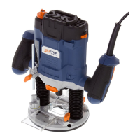
Installing edge guide
The edge guide is an effective aid to cutting in a straight line when chamfering or grooving.
Loosen two screws for edge guide.
Feed the bars on the edge guide through the holes in the base plate.
Adjust the distance between the router bit and the edge guide by moving the guide until it is at the correct distance.
Tighten the screws for edge guide to hold the edge guide in position.
Dust extraction
Dust extraction prevents large accumulations of dust, high concentrations of dust in the ambient air, and facilitates disposal.
For long periods of working with wood or for commercial use on materials that produce dust that is detrimental to health, the machine is to be
connected to a suitable external dust extraction device.
When using dust extraction, be sure that the vacuum cleaner is out of the way and secure so that it will not tip over or interfere with the router or
workpiece.
The vacuum hose and power cord must also be positioned so that they don’t interfere with the router or workpiece.
Turn on vacuum cleaner before router.
Empty the vacuum cleaner as necessary.
Coarse adjusting the depth cut
The depth of cut is the distance between the depth stop and the turret depth stop.
1. Loosen the locking screw so that depth stop can be moved freely.
2. Push down the plunge lock lever anti-clockwise and plunge the router down until the router bit touches the workpiece, then lock the router in
position by releasing the plunge lock lever.
3. Move the depth stop down against the turret depth stop and record the scale, set to “0”.
4. Adjust the depth stop to the required routing depth, push down the plunge lock lever anti-clockwise and guide the router back up again.
The coarse adjustment of the depth-of-cut should be checked by a trial cut and corrected, if necessary.
FINE ADJUSTING THE DEPTH OF CUT:
After a trial cut, fine adjustment can be carried out by turning the fine adjustment knob (1 scale mark = 0.1 mm/ 1 rotation = 2.0 mm).
Usage of the step buffer
1. Dividing the cutting procedure in several steps.
For deep cuts, it is recommended to carry out several cuts, each with less material removal. By using the step buffer, the cutting process can be divided
into several steps. Set the required depth-of-cut with the lowest step of the step buffer. Afterwards, the higher steps can be used for the first two cuts.
2. Pre-adjustment of varying depth-of-cuts.
If several different depth-of-cuts are required for the machining of a workpiece, these can also be pre-adjusted by using the step buffer.
24