Do you have a question about the Deye SUN-20K-G02-LV and is the answer not in the manual?
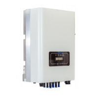
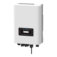
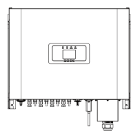
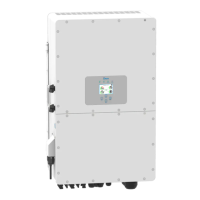
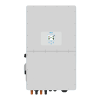
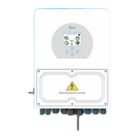
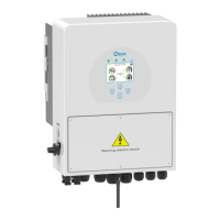
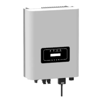
Describes the appearance of the on-grid inverter, including models like SUN-20K-G02-LV.
Explains various safety symbols used in the manual, highlighting potential risks like warning, shock, and high temperature hazards.
Provides essential safety instructions for electrical installation, handling, and operation to prevent injury or damage.
Offers important guidelines and precautions for operating the inverter safely and correctly, emphasizing qualified personnel and proper procedures.
Illustrates the front panel display of the inverter, showing the layout of status indicators and buttons.
Details the function of each LED status indicator light on the inverter's front panel (DC, AC, NORMAL, ALARM).
Explains the function of the four keys (Esc, Up, Down, Enter) on the inverter's front panel for navigation and setting modification.
Describes the information displayed on the two-line LCD screen, including status, data, service, and alarm messages.
Provides criteria for choosing a safe and suitable installation location, considering fire risk, ventilation, and sunlight exposure.
Details the process of mounting the inverter on a wall using the provided bracket and screws, ensuring proper orientation.
Guides on connecting the DC input terminals of the inverter, emphasizing polarity, voltage limits, and using approved connectors.
Explains how to connect the AC input terminals, including breaker specifications, cable types, and wiring procedures.
Details the importance and procedure for grounding the inverter to prevent surge voltage and EMI, including connections for single and multiple systems.
Recommends installing a circuit breaker to prevent overcurrent, providing specifications for the recommended protector.
Explains the wireless remote monitoring capability using a Wi-Fi Plug, connecting the inverter to the network for monitoring.
Describes the process of installing the datalogger accessory onto the inverter, including removing the sealing plate and securing it.
Refers to separate illustrations for configuring the installed datalogger, indicating it requires electrical connections and DC power.
Provides step-by-step instructions for starting the three-phase string inverter, including switching AC and DC breakers.
Details the correct procedure for shutting down the inverter, involving switching off AC and DC breakers in a specific order.
Explains using one meter for multiple inverters in parallel for zero export, detailing master/slave setup and RS485 connection.
Provides step-by-step instructions for setting up and enabling the zero-export function using the energy meter via the inverter's LCD.
Offers important suggestions and precautions for using the zero-export mode, focusing on PV array configuration and current sensor orientation.
Explains how to view load power and energy export on the monitoring platform after connecting the meter and setting up the system.
Details how to check PV power, voltage, grid voltage, inverter ID, model, and other information from the initial display.
Explains the five main submenus available in the inverter's main menu for accessing detailed information and settings.
Shows how to view LCD software version, control board software version, rated power, and communication addresses.
Explains that the inverter can store up to eight fault records, including time, for customer troubleshooting based on error codes.
Guides on how to turn the inverter ON or OFF from the menu, and what happens after the operation.
Explains the PV string current setting, noting that this function is optional and displays current for Branch 1 and Branch 2.
Introduces the five submenus within setup: system param, run param, protect param, comm param, for maintenance reference.
Covers settings related to time, language, display brightness, and factory reset options within the system parameters.
Notes that running parameters are password-protected and intended for authorized engineers only, with an initial password of 1234.
Details protection parameters that are engineer-only settings, dependent on safety requirements, and require a password.
Covers communication parameter settings, including address, baud rate, and meter type for establishing communication.
Details the 'PU' Mode for reactive power output, which varies in response to grid voltage, and lists associated parameters.
Explains the 'Q(U)' Mode where reactive power output varies with grid voltage, detailing parameters like Pstart, Pstop, Q1-Q6, V1-V6, and RMpTime.
Describes the 'Q(P)' Mode where reactive power output is controlled by active power, detailing parameters P1-P6 and Q1-Q6 for power regulation.
Explains the 'PF(P)' Mode where the power factor is controlled by active power, detailing parameters Ustart, Ustop, P1-P6, PF1-PF6, and RMpTime.
Lists various error codes displayed on the LCD screen, their descriptions, and suggested actions for troubleshooting common faults.
| Model | SUN-20K-G02-LV |
|---|---|
| Rated Power | 20 kW |
| Max. DC Input Voltage | 1100 V |
| Start-up Voltage | 200 V |
| Rated AC Output Power | 20 kW |
| Max. AC Apparent Power | 22 kVA |
| THDi | < 3% |
| DC Switch | Yes |
| Communication | RS485, Wi-Fi, GPRS |
| Frequency | 50/60 Hz |
| Number of MPPTs | 2 |
| Protection Level | IP65 |
| MPPT Voltage Range | 200 V - 1000 V |
| Nominal AC Voltage | 230V |
| AC Voltage Range | 180-280V |
| Operating Temperature Range | -25°C to 60°C |
| Output Voltage | 230V |
| Efficiency | 98.5% |
| Operating Temperature | -25°C to 60°C |
| Humidity | 0~100% |
| Protection | DC reverse polarity, AC short circuit, over temperature, over voltage, etc. |