Do you have a question about the Deye SUN-25K-SG01HP3-EU-BM2 and is the answer not in the manual?
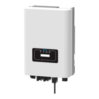
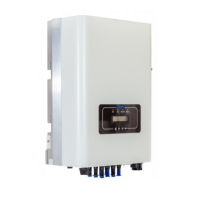
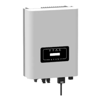
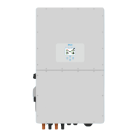
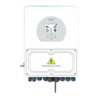
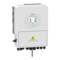
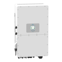
Details the physical components and ports of the hybrid inverter for identification.
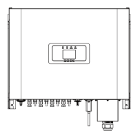
Provides dimensional drawings and specifications for the inverter and its mounting bracket.
Lists the key technical capabilities and functionalities of the hybrid inverter.
Illustrates a typical system configuration showing how the inverter connects to solar, battery, grid, and load.
Enumerates all components included in the inverter package for installation.
Details precautions and site selection criteria for safely installing the hybrid inverter.
Explains how to safely connect the battery to the inverter, including cable sizing and connector assembly.
Details the purpose and pin assignments for various communication and control ports on the inverter.
Guides on connecting the inverter to the grid and backup load, specifying breaker sizes and wiring.
Provides instructions and safety guidelines for connecting photovoltaic (PV) modules to the inverter.
Covers selecting appropriate PV modules and connecting them to the inverter safely and correctly.
Details the wiring procedure for Current Transformers (CTs) used for power monitoring.
Illustrates how to connect the CHNT DTSU666 and Eastron meters for system monitoring.
Explains the mandatory grounding procedure for safety and protection against electric shock.
Briefly mentions referring to Wi-Fi Plug illustrations for its configuration.
Provides a general wiring diagram example for various system configurations including battery, PV, load, and grid.
Presents detailed wiring diagrams for on-grid and off-grid applications, including backup and home loads.
Illustrates the typical application of connecting a diesel generator to the inverter system.
Shows how to connect multiple inverters in parallel for increased power output.
Describes the procedure for turning the inverter on and off using the dedicated button.
Explains the inverter's front panel, including LED indicators and function buttons.
Details the information displayed on the inverter's main touchscreen, including system status and energy flow.
Maps out the navigation paths between different screens and menus on the inverter's LCD.
Shows how to view daily, monthly, and yearly solar power generation data on the LCD.
Displays solar, load, grid power curves and detailed battery status including Li-BMS information.
Introduces the main categories within the system setup, such as Battery, Grid, and Basic settings.
Covers settings like time synchronization, beep options, auto-dim, factory reset, and lockout.
Allows configuration of battery mode, capacity, charging parameters, and activation.
Configures operational modes like Selling First, Zero Export, and Grid Peak Shaving.
Manages grid connection parameters, including mode selection, voltage, frequency, and protection settings.
Configures the generator input port for various modes like SmartLoad output and Micro Inverter input.
Enables specific functions like Solar Arc Fault detection, Gen Peak-shaving, and Signal Island mode.
Displays inverter ID, firmware versions, and alarm codes.
Illustrates the basic system setup with solar and battery connections.
Shows a system configuration that includes a generator for backup power.
Depicts a system configuration utilizing a smart load for optimized power management.
Illustrates an AC couple setup for connecting the inverter to an existing AC system.
| Model | SUN-25K-SG01HP3-EU-BM2 |
|---|---|
| Type | Hybrid Inverter |
| Rated Output Power | 25000 W |
| Max. DC Input Voltage | 1000V |
| Start Voltage | 250 V |
| Number of MPPT Trackers | 2 |
| Number of Strings per MPPT Tracker | 2 |
| Max. Input Current per MPPT Tracker | 26 A |
| Rated AC Output Power | 25000 W |
| Max. AC Output Power | 27500 W |
| Max. AC Output Current | 40 A |
| Grid Frequency | 50/60Hz |
| Total Harmonic Distortion (THD) | <3% |
| Max. DC Input Short-Circuit Current | 40 A |
| Max. Charging Current | 50 A |
| Max. Discharging Current | 50 A |
| Protection Degree | IP65 |
| Input Voltage Range | 200 V - 1000 V |
| AC Voltage Range | 180-280Vac |
| AC Grid Connection Type | 3-phase |
| Communication | RS485, WiFi, Ethernet |
| Operating Temperature Range | -25°C to 60°C |
| Dimensions | 680 x 500 x 230 mm |
| Operating Temperature | -25°C to 60°C |
| Humidity | 0-100% (non-condensing) |
| Max. DC Input Power | 37.5kW |
| Max. Charging Power | 2.5kW |
| Max. Discharging Power | 2.5kW |