Do you have a question about the Deye SUN-70K-G03 and is the answer not in the manual?
Describes product information, installation, operation, and maintenance guidelines for the PV system.
Provides guidance on reading the manual and other documents before operating the inverter for safe and effective use.
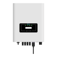
On-grid inverter converts solar panel DC power into AC power. It supports models SUN-70K-G03 to SUN-110K-G03.
Lists all included components in the package, such as the inverter, mounting bracket, screws, and tools.
Explains the meaning of safety symbols used in the manual, including warnings, shock hazards, and temperature warnings.
Provides essential safety guidelines for electrical installation and inverter operation, emphasizing qualified personnel and proper procedures.
Outlines important operational requirements and precautions for safe use of the inverter, including installation and handling guidelines.
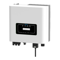
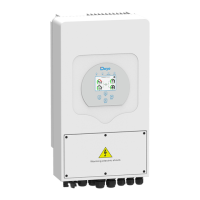
Illustrates the front panel display of the inverter, showing indicators, buttons, and the LCD screen.
Details the function of the four indicator lights (DC, AC, NORMAL, ALARM) and their status meanings.
Describes the four buttons on the inverter panel (UP, DOWN, ESC, ENTER) and their functions for navigation and parameter adjustment.
Explains the content displayed on the inverter's 256*128 dot formation display, including status, operating information, and warnings.
Provides criteria for choosing a suitable installation location, considering fire risk, ventilation, overheating, and sunlight exposure.
Specifies the correct installation angle (+/-15°) and required spacing between inverters for optimal performance and safety.
Details the required installation gap around the inverter and provides dimensions for the mounting bracket for proper installation.
Provides step-by-step instructions for mounting the inverter onto a wall using expansion bolts and ensuring correct alignment.
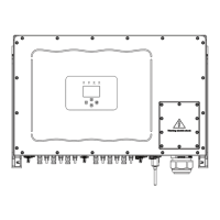
Guides on safely connecting the DC input terminals, including polarity, voltage limits, and cable specifications.
Details the connection of AC cables to the inverter terminals, specifying wire types and connection points for L1, L2, L3, N, and PE.
Provides a table of recommended current protection devices (fuses/breakers) for each inverter model based on their rated output power.
Explains the importance of proper grounding for surge protection and EMI performance, detailing connection methods for single and multiple systems.
Describes how to connect the inverter to a network for remote monitoring using the Wifi function and optional Datalogger.
Provides instructions for installing the datalogger by replacing the sealing plate and connecting it to the inverter's interface.
Refers to illustrations for configuring the datalogger after installation, ensuring proper data collection and reporting.
Details the step-by-step procedure for safely starting up the inverter, including switching AC and DC breakers and verifying parameters.
Outlines the procedure for safely shutting down the inverter, involving switching off AC and DC breakers and waiting for discharge.
Describes how to configure multiple inverters in parallel for zero-export function using a single meter, designating a master and slaves.
Explains how to view PV load power and export energy on the solarman monitoring platform after proper setup and meter connection.
Describes the inverter's LCD display during normal operation, showing power, generation, and status information.
Details accessing statistics like energy generation, fault records, and ON/OFF settings for system monitoring.
Explains how to turn the inverter ON or OFF through the menu interface, including confirmation steps.
Covers configuration of system, running, protection, and communication parameters for optimal inverter performance.
Explains the inverter's over-frequency response function, its parameters like StartPoint, StopPoint, and RecoverPoint.
Explains the inverter's reactive power regulation function, detailing modes like PF, Q(U), Q(P), and PU for grid support.
Details protection parameters for various grid standards (INMETRO, EN50549, etc.) and custom settings for voltage and frequency protection.
Provides guidance on cleaning and maintaining the inverter, emphasizing safety precautions like turning off power and using soft materials.
Lists and explains various error codes displayed on the inverter, along with troubleshooting steps and contact information for support.
| Model | SUN-70K-G03 |
|---|---|
| Start-up Voltage | 250 V |
| Number of MPP Trackers | 6 |
| Number of Strings per MPP Tracker | 2 |
| Max. Input Current per MPPT | 26 A |
| Rated AC Voltage | 400 V |
| Grid Frequency | 50/60Hz |
| Total Harmonic Distortion (THDi) | <3% |
| Power Factor | 0.8 leading to 0.8 lagging |
| DC Switch | Yes |
| Max Efficiency | 98.6% |
| Protection Degree | IP66 |
| Type | Three-phase |
| Rated Output Power | 70000 W |
| Max. DC Input Voltage | 1100V |
| Max. AC Apparent Power | 77, 000 VA |
| AC Voltage Range | 320 V - 480 V |
| Rated Grid Voltage | 400 V |
| Protection | DC reverse polarity |
| Operating Temperature Range | -25°C to +60°C |
| Cooling | Smart cooling |
| Communication | RS485 |
| Max. DC Input Power | 105, 000 W |
| MPPT Voltage Range | 200-1000V |