Do you have a question about the DG Flugzeugbau DG200 and is the answer not in the manual?
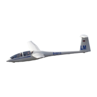
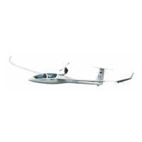
Contains details about the basic design of the aircraft.
Lists approved variations of the basic aircraft design.
Provides a detailed description of the Bohli compass.
Instructions for installing the Bohli compass.
Details on how to mount the instrument.
Explains how to level the compass for accurate readings.
Instructions for maintaining and caring for the compass.
Specific information for using the compass in the southern hemisphere.
Describes the applications of the altimeter.
Provides technical specifications for the altimeter.
Information regarding the altimeter's scale ring.
Describes the applications of the airspeed indicator.
Provides technical specifications for the airspeed indicator.
Lists commonly used airspeeds in aviation.
Explains the application of the variable-flap ring.
Highlights the features of the airspeed indicator with the ring.
Instructions on how to use the airspeed indicator with the ring.
Describes the applications of the variometer.
Provides technical specifications for the variometer.
Maintenance instructions for the variometer.
Lists the technical data for the DX 50.
Explains the variometer system functions.
Details the electronic altitude meter functionality.
Describes the GPS navigation capabilities.
Information on the flight computer's calculations.
Details on the flight route drawing feature.
Information on the airfield and turnpoint database.
Explains how to enter and manage coordinates.
Information regarding aircraft poles.
Introduction to the AR 3201 transceiver handbooks.
Describes the intended purpose of the AR 3201 transceiver.
Provides a general description of the AR 3201 transceiver.
Surveys the different variants of the AR 3201 transceiver.
Details the specifications of the AR 3201 transceiver.
General data for the AR 3201 transceiver.
Technical specifications for the receiver.
Technical specifications for the transmitter.
Lists optional functions available for the transceiver.
Details the certifications obtained by the transceiver.
Lists necessary accessories for the transceiver.
Details what is included in the scope of delivery.
Information about the transceiver's software.
General guidelines for installation.
Checks to perform before installation.
Procedures for the mechanical installation.
Instructions for wiring the transceiver.
Details on connecting the optional auxiliary audio input.
Steps for testing the transceiver after installation.
General installation applicability.
Procedure to check units for transit damage.
General pre-installation check.
Performing a visual inspection before commissioning.
Details on mechanical installation.
Installing the VHF transceiver into the panel.
Installing the temperature sensor.
Wiring the VHF transceiver.
General wiring instructions.
Connecting the microphone to the transceiver.
Connecting speakers or headphones.
Connecting for intercommunication.
Connecting the panel lighting circuit.
Connecting other audio equipment.
Testing procedures after installation.
Performing ground tests with the engine off.
Performing ground tests with the engine on.
Identifies and explains the transceiver's controls and indicators.
Operating instructions for specific serial number ranges.
Operating instructions for serial numbers 4000 and above.
How to store channel frequencies.
Procedures for setting the emergency frequency.
Explains LC display blinking indications.
Instructions for intercommunication (IC) operation.
Operating optional temperature and voltage measurements.
Using the optional auxiliary audio input.
Information on channel frequency storage limitations.
Safety precautions for transceiver operation.
Detailed explanation of controls and indicators.
Operating procedures for earlier models.
Operating procedures for later models.
Steps for storing frequencies in memory.
How to set the emergency frequency.
Emergency frequency setting for older models.
Emergency frequency setting for newer models.
Interpreting LC display blinking signals.
How to operate the intercommunication feature.
Using optional measurement features.
Connecting external audio sources.
Information on frequency storage limitations.
Safety precautions for transceiver operation.
Overview of the manual's purpose.
Technical specifications of the DX 50.
Highlights differences between DX 50 FAI and DX 50 models.
Explains the functions of the variometer system.
Details the electronic altitude meter functionality.
Describes the GPS navigation system.
Information on the flight computer's calculations.
How the DX 50 records flight paths.
Details on the airport and turning point database.
Instructions for entering and managing coordinates.
Information on selecting and defining glider polars.
Methods for mechanically fixing the DX 50.
Guidance on mounting the GPS antenna.
Details on pneumatic connections.
Wiring instructions for the DX 50.
Identifies and describes the DX 50's control elements.
Detailed functions of the control elements.
Procedures for editing and selecting data.
Editing and selecting data using the interface.
How to adjust the wing load setting.
Instructions for inputting McCready values.
Details the first glider navigation display.
Describes the graphic display for navigation.
Information on the navigation display.
Shows arrival data for waypoints.
Provides airport approach information.
Displays current position, time, and stopwatch.
Shows nearest airports and courses.
For direct airport approach or database editing.
For direct turning point approach or database editing.
For flying and editing programmed tasks.
Accesses flight statistics and logbook data.
For system setup and configuration.
Enables group flights and partner tracking.
Options for wind calculation.
Allows quick storage of current position as a turning point.
How to select and activate a programmed task.
Procedures for editing and modifying tasks.
Step-by-step guide to programming a new task.
How to delete a programmed task.
Guidance on flying with a programmed task.
How to start a programmed task.
Procedures for restarting a task.
Guides the user through the system setup program.
Settings related to task modes, radius, and cylinder.
GPS settings including time offset and datum.
Selection of desired units for data presentation.
Options for glider symbol size.
Configuring airspace display settings.
Entering new QNH values for altitude correction.
Settings for the FAI Logger.
Initialization parameters for variometer and speed command.
Adjusting display contrast and lighting.
Procedures for PC communication and data transfer.
Setting or entering the password for submenus.
Task settings for mode, radius, and cylinder.
GPS settings for time display and datum.
Selecting units for various flight data.
Adjusting the glider symbol size.
Configuring airspace display settings.
Configuring NMEA data strings for external devices.
Setting communication baudrate for PC connection.
Selecting and activating glider polars.
Setting electronic compensation for the TE probe.
Configuring audio signals for variometer and speed command.
Selecting analog functions and probe settings.
Configuring the variometer indicator.
Provides flight statistics and graphical presentation.
Displays flight data and logbook entries.
Shows available flight data after task completion.
Details on connecting cables for the system.
Technical drawing showing drilling specifications.
Provides brief notes and keyboard shortcuts.
Welcome message and introduction to FLARM.
Explains the operational principles of FLARM.
Provides essential advice for operating FLARM.
Describes the different operating modes of FLARM.
Details the components and layout of the FLARM front panel.
Instructions for starting up the FLARM unit.
Guides on identifying and resolving faults.
Explains the meaning of the status LEDs.
Details the functions of the push button.
Information on anti-collision warnings.
Further details on collision warnings.
Information regarding warnings for obstacles.
Outlines the operational limitations of FLARM.
Recording weight and balance data.
Details control surface displacements and tolerances.
Outlines various inspection procedures.
Instructions for exchanging waterbags.
Procedures for repairing damage to the aircraft.
Guidelines for servicing and caring for the aircraft.
Details on lubrication points and procedures.
Lists the materials used in the DG-200 construction.
A checklist for post-crash landing inspections.
Instructions for performing repairs.
Information on control surface mass balancing.
Checks for play in control systems.
Repair instructions for the bowden cable mechanism.
Checking tangential play in the wings.
Checking tangential play in wing tips.
Lists all instruments and equipment installed in the aircraft.
Specifications related to the wing.
Information on angles of incidence.
Tolerances for rudder control surface.
Tolerances for elevator control surface.
Details about aileron and flap controls.
Tolerances for aileron control surface.
Tolerances for flap control surface.
Inspections based on flight hours and annual checks.
Checking play in ailerons and flaps.
Inspection of the control mechanism.
Occasional inspection items.
Procedure to increase aircraft service time.
Instructions for exchanging waterbags.
General checks for the entire aircraft.
Specific checks for the wings.
Inspection of the wing root rib.
Inspection of the aircraft shell.
Checks for ailerons and flaps.
Procedure for checking fuselage torsion.
Inspection at the fuselage and stabilizer intersection.
Checks related to stabilizer mounting.
Inspection of rudder bearings.
Checks for the tail wheel.
Inspection of the fuselage shell.
Inspection of the tow hook.
Inspection of the seat back rest bulkhead.
Checks for the seat belt.
Checking the stick for play.
Inspection of flight controls.
Checks for instruments.
Lists repairable parts and damage.
Describes the method for FRP repairs.
Details overlap dimensions for repairs.
Explains the method of beveled repair.
Details on individual control surfaces.
Procedures for measuring mass balancing moments.
Measuring rudder mass balancing moments.
Measuring elevator mass balancing moments.
Measuring aileron mass balancing moments.
Measuring wing flap mass balancing moments.
Checking for play in ailerons.
Checking for play in the elevator.
Checking for play in flaps.
Checking for play in the rudder.
Repairing the bowden cable in the stick mechanism.
Checking tangential play in wing tips.
List of airspeed indicators.
List of altimeters.
Details on safety belts and harnesses.
List of radios installed.
| Brand | DG Flugzeugbau |
|---|---|
| Model | DG200 |
| Category | Aircrafts |
| Language | English |