6
Step
1
3
5
X 2
X 2
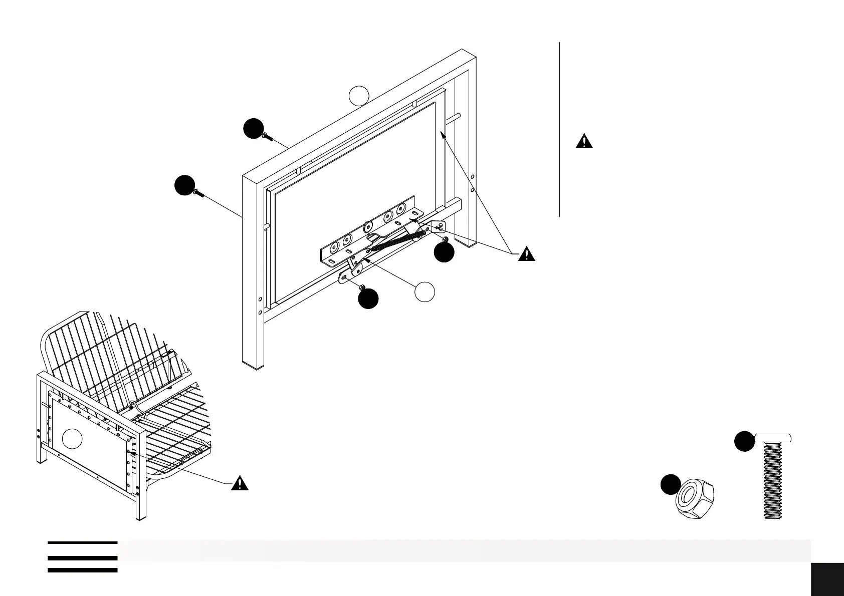
Attach L to A with and ;
The top of Mechanism L may look
different due to the movable joints.
Please determine the orientation based
on their bottom sides.
A
L
5
5
3
3
Mechanism L should be attached on
the inside of Arm A that without nail
heads.
A
Nail heads on Arm A towards outside.