EasyManua.ls Logo

Diablo DSP-7LP - User Manual

Diablo DSP-7LP
25 pages
Print Icon
To Next Page IconTo Next Page
Loading...
DSP-22-2_MAN_E 12/10/2020 Page 1 of 25 Pros Who Know Trust Diablo
User Manual
DSP-22-2
Low Power, Dual Channel Vehicle
Detector with Support for the
Free Exit Probe
Question and Answer IconNeed help?

Do you have a question about the Diablo DSP-7LP and is the answer not in the manual?

Summary

Introduction

Functional Data

Details user-selectable sensitivities and four frequency settings for both channels.

Electrical Data

Specifies operating voltage, current draw, and output ratings for solid state and relay outputs.

Environmental Data

Outlines operating and storage temperature ranges and humidity limits.

Mechanical Data

Provides physical dimensions, housing material, and mounting position information.

Features and Functions

Detector Reset Procedure

Explains the reset process triggered by DIP switch changes, button press, or power cycle.

Channel 1 Enable;Disable

Describes how to enable or disable Channel 1 using DIP Switch 9.

Channel 1 Sensitivity Settings

Details the four sensitivity levels for Channel 1 using DIP Switches 1 and 2.

Channel 1 Sensitivity Boost

Explains the feature to increase Channel 1 sensitivity after initial detection.

Channel 1 Frequency Settings

Details the four frequency settings for Channel 1 using S3 DIP Switches 1 and 2.

Channel 2 Enable;Disable

Describes how to enable or disable Channel 2 using DIP Switch 10.

Channel 2 Sensitivity Settings

Details the four sensitivity levels for Channel 2 using DIP Switches 4 and 5.

Channel 2 Sensitivity Boost

Explains the feature to increase Channel 2 sensitivity after initial detection.

Channel 2 Presence;Pulse Modes

Explains the Presence and Pulse modes for Channel 2 operation.

Channel 2 Loop or Probe Selection

Details selection between inductive loop and Free-Exit Probe for Channel 2.

Channel 2 Frequency Settings

Details the four frequency settings for Channel 2 using S3 DIP Switches 3 and 4.

LED Indicators Overview

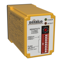
Describes the states and meanings of the Power, Detect 1, and Detect 2 LEDs.

Installation Procedures

Inductive Loop Best Practices

Provides rules for wire material, gauge, connections, saw cuts, and loop placement.

Detector Unit Installation

Details the location and mounting of the detector unit on the operator.

Loop Installation Guide

Covers wire type, gauge, configuration, and installation practices for road loops.

Free Exit Probe Installation

Details the installation process for the Free Exit Probe, including placement and sealant.

Troubleshooting Guide

Troubleshooting: No Power LED

Steps to diagnose and resolve issues when the Power LED is off.

Troubleshooting: Detect LED Flash (Once;2 Sec)

Diagnoses open loop, high resistance, or excessive inductance faults.

Troubleshooting: Detect LED Flash (Twice;2 Sec)

Diagnoses shorted loop, low resistance, or insufficient inductance faults.

Troubleshooting: Detect LED Flash with Power LED

Addresses intermittent failures, often related to loop connections or fatigue.

Troubleshooting: Intermittent Power LED

Identifies issues related to electrical interference affecting the Power LED.

Troubleshooting: False Detections (Detect LED)

Diagnoses issues causing false detections due to loop problems or proximity.

Troubleshooting: No Detect LED Activity

Steps to take when the Detect LED does not illuminate with a vehicle present.

Troubleshooting: Detect LEDs Flash Back and Forth

Explains the meaning of Detect 1 and Detect 2 LEDs flashing when channels are disabled.

Overview

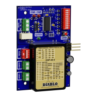
The DSP-22-2 is a low-power, dual-channel vehicle detector designed to work with both inductive loops and the new Diablo Control Free Exit Probe. It is powered by a high-performance 8-bit microcontroller and features a small footprint, making it suitable for direct integration into many DoorKing operators.

Function Description

The DSP-22-2 serves as a vehicle detection system, offering two independent channels that can be configured for various operational modes. Each channel can be enabled or disabled independently, and their sensitivity and frequency settings are user-selectable. Channel 1 provides a solid-state output, while Channel 2 offers relay outputs with separate screw terminals for wired connections.

The detector supports both presence and pulse modes of operation. In presence mode, the output remains activated as long as a vehicle is detected over the loop, with an extended presence mode that can hold weak detections for up to 15 minutes and strong detections for days or weeks, provided power is uninterrupted. In pulse mode, a 250-millisecond pulse is generated when a vehicle first enters the loop. The device also supports a "Pulse with 1-second retune" mode when operating with a free-exit probe, where the channel retunes after 1 second, potentially generating additional pulses if the vehicle remains over the probe.

A key feature is the ability to increase sensitivity after initial detection (Sensitivity Boost), which is useful for detecting high-bed tractor-trailer vehicles without being overly sensitive to false detections. The detector also incorporates frequency adjustment capabilities for each channel to mitigate inductive coupling and interference when multiple loops are installed in close proximity.

Important Technical Specifications

Loop Inductance:

  • Range: 20 microhenries to 1500 microhenries (including lead-in inductance).
  • Note: Not all frequency settings are available at inductances below 30 microhenries.
  • Ideal Loop Inductance: 50 to 500 microhenries for stable operation.

Operating Voltage:

  • 14 volts to 27 volts DC.

Solid State Output (Channel 1):

  • Maximum Output Current: 250 milliamps.
  • Maximum Pull-Up Voltage: 30 volts.
  • Maximum Voltage Drop Across Active Output: 0.3 volts.

Relay Output (Channel 2):

  • 30 VDC, 2 amps (resistive).
  • 110 VDC, 0.3 amps (resistive).
  • 125 VAC, 0.5 amps (resistive).

Current Draw (typical @ 20VDC):

  • No Channel in Detect: 1.62 milliamps.
  • Channel 1 in Detect: 23.94 milliamps.
  • Channel 2 in Detect: 30.75 milliamps.
  • Both Channels in Detect: 33.60 milliamps.

Environmental Data:

  • Operating Temperature: -35°F to 165°F (-37°C to 74°C).
  • Storage Temperature: -40°F to 176°F (-40°C to 80°C).
  • Humidity: Up to 95% relative humidity non-condensing.

Physical Dimensions:

  • High: 4.300 inches (109.22 mm).
  • Wide: 2.950 inches (74.93 mm).
  • Deep: 0.820 inches (20.83 mm).
  • Housing Material: Lexan.

Pulse Output:

  • 250ms ±15ms.

Response Time:

  • 181 ms typical, 314 ms worst case.

Usage Features

Sensitivity Settings:

  • Four user-selectable sensitivity levels for each channel, ranging from 0.32% ΔL/L Low to 0.04% ΔL/L High.
  • Factory default for Channel 1 is Low (0.32% ΔL/L Low).
  • Sensitivity Boost feature for Channel 1 and Channel 2 allows increased sensitivity after initial detection, beneficial for high-bed vehicles.

Frequency Settings:

  • Four user-selectable frequency settings (High, Medium High, Medium Low, Low) for each channel to prevent interference between loops, especially when installed close together.

Channel Enable/Disable:

  • DIP switches allow independent enabling or disabling of Channel 1 (DIP Switch 9) and Channel 2 (DIP Switch 10).
  • Factory default for both channels is enabled.

Operating Modes (Channel 2):

  • Presence Mode: Output remains active as long as a vehicle is detected.
  • Pulse Mode: Generates a 250ms pulse on vehicle entry.
  • Loop/Probe Selection: Channel 2 can operate with a standard inductive loop or a Free-Exit Probe (magnetometer).
  • Probe Mode: Only pulse on entry operation is available, regardless of other settings. Detection is held for 1 second.

Indicators:

  • Three LEDs: Power (Green), Detect 1 (Red), and Detect 2 (Red).
  • Power LED:
    • Off: Voltage below 3 volts.
    • Reset: Flashes during reset event (500ms off, 500ms on, 500ms off).
    • High Speed Operation: Always on.
    • Low Power Operation: Blinks once every 2 seconds.
  • Detect LEDs (1 & 2):
    • Off: No vehicle, normal loop function, no prior fault in last week.
    • Reset in Fail-safe/Fail-secure: Specific flash patterns during reset.
    • Detect: Constantly on when a vehicle is detected.
    • Open Loop Fault: Flashes once every 2 seconds.
    • Shorted Loop Fault: Flashes twice every 2 seconds.
    • Large Change Fault: Flashes three times every 2 seconds.
    • Prior Fault: Flashes one, two, or three times depending on fault type (in high-speed mode) or flashes simultaneously with Power LED (in low power mode).
    • Pulse Occupancy (Detect 2): Flickers rapidly when in pulse mode, vehicle present, but output not active.
    • Detect 1 and Detect 2 Flash Back and Forth: Occurs when both channels are disabled (DIP switches 9 & 10 OFF), indicating a non-normal operating mode.

Maintenance Features

Detector Reset:

  • Automatically performed when DIP switches are changed, the reset button is pressed, or power is cycled. This allows the detector to re-initialize and stabilize.

Troubleshooting Guidance:

  • No Power LED: Check voltage (14-27V DC). If voltage is correct, replace detector.
  • Detect LED Flashes Once Every Two Seconds (Open Loop):
    • Verify loop connection to correct terminals.
    • Check loop circuit resistance with an ohmmeter (typically 1.5 ohms or less; above 5 ohms indicates a bad connection or damaged wire).
    • Check loop inductance with an inductance meter (should be less than 1500 microhenries).
    • If another operating detector is available, swap loops to isolate the problem.
  • Detect LED Flashes Twice Every Two Seconds (Shorted Loop):
    • Verify loop connection.
    • Disconnect loop wires; LED should flash once every two seconds. If not, replace detector.
    • Check loop circuit resistance (below 0.2 ohms indicates a short; typically 0.5-1.5 ohms).
    • Check loop inductance (should be more than 20 microhenries; less indicates incorrect winding or damage).
    • Swap loops with a working detector to isolate the problem.
  • Detect LED Flashes at Same Time as Power LED (Prior Fault):
    • Indicates a past failure that is now resolved.
    • Suggests intermittent open loop faults (check splices, wire nuts, fatigued wire at expansion joints or conduits).
    • Could also be intermittent shorted loop faults (check for foreign objects, damaged wire insulation).
  • Power LED Intermittently Comes On (Not Once Every 2 Seconds):
    • Indicates electrical interference (cross-talk, external noise sources like radio transmitters, card readers, electric motors).
    • Adjust loop frequencies to mitigate cross-talk.
    • Identify and turn off potential interference sources.
    • Ensure lead-in wires are tightly twisted.
  • Detect LED Intermittently Comes On / Stays On Without Vehicle:
    • Caused by physical loop issues, electrical interference, or moving objects near the loop.
    • Physical Issues: Use a megohmmeter to check insulation resistance (should be at least 100 megohms; below 50 megohms indicates compromised insulation).
    • Electrical Interference: Adjust loop frequencies, identify and remove noise sources, ensure proper wire twisting.
    • Moving Objects: Relocate detection area away from moving gates (at least 4 feet), lower sensitivity if possible, secure manhole covers.
  • Detect LED Will Not Come On With Vehicle:
    • Perform a lamp test by pressing the RESET button (all LEDs should turn off and then on). If a Detect LED does not illuminate, replace the detector.
    • Adjust sensitivity to a higher level if needed.
    • Swap loops with a working detector to isolate the problem.
  • Detect 1 and Detect 2 LEDs Flash Back and Forth:
    • Occurs when both channels are disabled (DIP switches 9 & 10 OFF).
    • This is a diagnostic mode; enable at least one channel to stop the display.

Loop Installation Best Practices:

  • Use cross-linked polyethylene (XHHN or XHHW) insulated wire; avoid PVC (THHN).
  • Larger wire gauge (e.g., 14 or 12 AWG) for heavy traffic or asphalt installations.
  • Crimp or solder wire connections; avoid wire nuts.
  • Miter saw cuts at 45 degrees to reduce wire bend angle.
  • Use backer rod to hold loop wire at the bottom of saw cuts.
  • Allow slack wire at expansion joints.
  • Twist lead-in wires (3-6 twists per foot) tightly to reduce electrical interference.
  • Connect multiple loops in series (not parallel) to the same channel; ensure they are the same size, shape, and number of turns.
  • Use appropriate loop sealant for the roadway surface.
  • Clean saw slots thoroughly before sealing.

Diablo DSP-7LP Specifications

General IconGeneral
BrandDiablo
ModelDSP-7LP
CategorySecurity Sensors
LanguageEnglish

Related product manuals