Page 9;&(%$*4.8"4,7%<'*#$"&8#=%/7*,#*%4,77%>?@@@?@AA?BCDC1Item 64683
EF;6GHIJ6KFGLIMNFLMG6MFMO6 E6GPJ
L8#$,77"83%E/7,#.%R',(9#
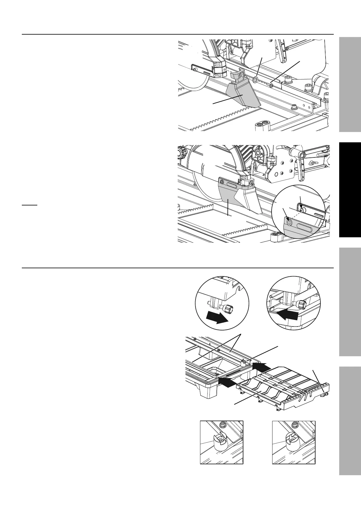
1. Attach the Rear Splash Guard (40) to the back
of the Blade Guard with a Ø5 Flat Washer (11)
and M5 x 16 Pan Head Screw (14).
2. Align the hole on each end of the Side
Splash Guard (39) to the screw on each
side of the Blade Guard and press the holes
on the Splash Guard over the screws.
M&$*- It is not necessary to loosen or
remove the screws on the Blade Guard
to install the Side Splash Guard.
L8#$,77"83%$.*%G,+7*
1. On the right side of the Table (61),
pull the Table Lock Lever (83) out.
Rotate the Toggle Table Stop
(118) to the unlock position.
2. Hold the Table parallel with the Water
Tray Frame (5), set the Table rollers
on the Frame rails and push the Table
toward the back of the saw.
3. Push the Table back along the Frame
rails until the final set of rollers
engage the rails. Rotate the Toggle
Table Stop to the lock position.
G,+7*%L8#$,77,$"&8
G&337*%
G,+7*%
E$&/
G&337*%G,+7*%
E$&/
G,+7*%
T&4`%
T*W*(
G,+7*%T&4`%
T*W*(
G,+7*
T&4`
P87&4`
T&4`P87&4`
;(,5*%
K,"7#
K*,(%
E/7,#.%
R',(9
E"9*%E/7,#.%
R',(9
S7,9*%
R',(9
S7,9*%
R',(9
M5 x 16
E4(*)
Ø
B%
Q,#.*(
]&7*
E4(*)
E/7,#.%R',(9%L8#$,77,$"&8