Page 9;&(%$*4.8"4,7%<'*#$"&8#=%/7*,#*%4,77%>?@@@?@AA?BCDC1Item 64684
EF;6GHIJ6KFGLIMNFLMG6MFMO6 E6GPJ
FEE6NSTH
GI%JK6!6MG%E6KLIPE%LMbPKH%;KIN%FOOLU6MGFT%IJ6KFGLIM-%
G'(8%$.*%J&)*(%E)"$4.%&2%$.*%$&&7%&22%,89%'8/7'3%$.*%$&&7%2(&5%"$#%*7*4$("4,7%&'$7*$%
+*2&(*%/*(2&(5"83%,8V%/(&4*9'(*%"8%$."#%#*4$"&81
M&$*- For additional information regarding the parts listed in the following pages,
refer to the Assembly Diagram near the end of this manual.
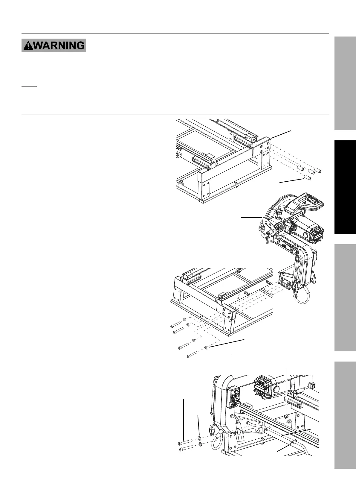
L8#$,77"83%N&$&(%X*,9
1. Place four Sleeves (4) into top mounting holes
on side of Water Tray Frame (5) as shown.
2. Align the holes in the Motor Head Assembly
with the corresponding mounting holes
on the side of the Water Tray Frame.
3. Insert four M10 x 50 Socket Head Cap Screws (1)
through four Flat Washers (2). Insert through
mounting holes on end of Water Tray Frame and into
Motor Head Assembly, as shown. Finger tighten.
4. Insert two M10 x 70 Socket Head Cap
Screws (153) through two Flat Washers,
and then into holes on side of Motor Head.
Secure using M10 Lock Nuts (7).
5. Place Clear Hose from Motor Head Assembly
into two Hose Clamps (6) on Frame. Squeeze
Clamps together to secure Hose.
6. Tighten previously installed M10 x 50
Socket Head Cap Screws securely.
Q,$*(%
G(,V%
;(,5*
E7**W*%
N&$&(%
X*,9%
F##*5+7V
M10 x 50
O,/%E4(*)
N>Z%
T&4_%M'$
M10 x 70
O,/%E4(*)
X&#*%
O7,5/
X&#*
;7,$%
Q,#.*(
;7,$%Q,#.*(
N&$&(%X*,9%L8#$,77,$"&8