Page 10 ;&(%$*4.8"4,7%<'*#$"&8#=%/7*,#*%4,77%>?@@@?@AA?BCDC1 Item 64684
EF;6GH IJ6KFGLIM NFLMG6MFMO6E6GPJ
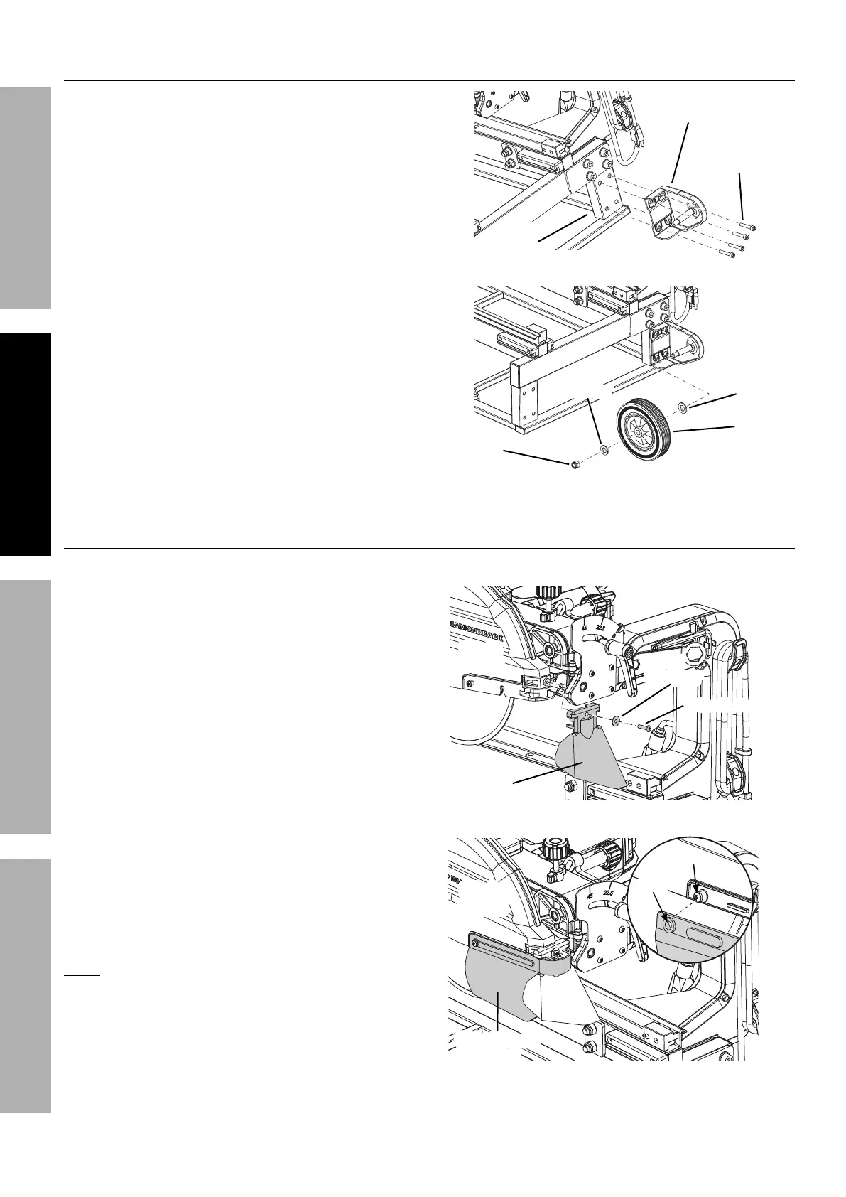
Q.**7%L8#$,77,$"&8
1. Align the holes in the Right Wheel Bracket (174)
with the corresponding mounting holes on the
side of the Water Tray Frame. Insert four M6 x 30
Socket Head Cap Screws (175) through the
Bracket into the Frame and tighten securely.
2. Slide one Ø12.5 Washer (172), Wheel (173), and
Ø10 Flat Washer (2) onto the axle on the Wheel
Bracket. Secure in place with an M10 Lock Nut (7).
3. Repeat procedure with the Left Wheel
Bracket (157) and second Wheel.
Q,$*(%
G(,V%
;(,5*
Q.**7%
K"3.$%Q.**7%
S(,4_*$
N>Z%
T&4_%M'$
M6 x 30
O,/%E4(*)
Ø>[1B%
Q,#.*(
Ø>Z%
Q,#.*(
Q.**7%L8#$,77,$"&8
L8#$,77"83%E/7,#.%R',(9#
1. Attach the Rear Splash Guard (110) to the back
of the Blade Guard with a Ø5 Flat Washer (108)
and M5 x 12 Pan Head Screw (40).
2. Align the hole on each end of the Side Splash
Guard (107) to the screw on each side of
the Blade Guard and press the holes on
the Splash Guard through the screws.
M&$*- It is not necessary to loosen or
remove the screws on the Blade Guard
to install the Side Splash Guard.
K*,(%
E/7,#.%
R',(9
E"9*%E/7,#.%
R',(9
S7,9*%
R',(9
S7,9*%
R',(9
M5 x 12 Screw
Ø
B%
Q,#.*(
X&7*
E4(*)
E/7,#.%R',(9%L8#$,77,$"&8