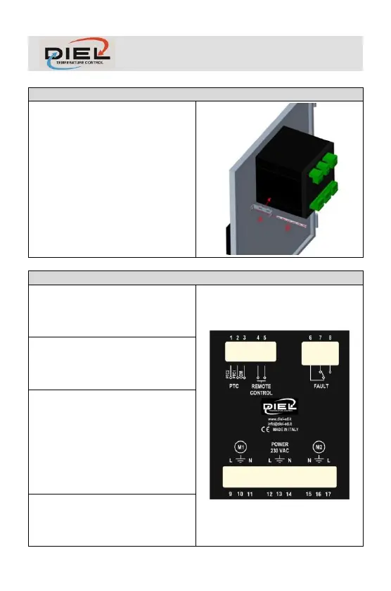
Make a 91X91 mm hole in the panel,
fix the control unit with the supplied
hooks.
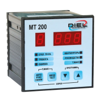
POWER SUPPLY AND ELECTRICAL CONNECTIONS
Terminals 1-2-3: Connection for 2
PTC probes, terminal 1 PTC2 probe,
terminal 2 PTC1 probe, terminal 3
common.
Terminals 4-5: Remote control, upon
closing of the contact, in case of
automatic operation, the ventilation
lines will be enabled.
Terminals 6-7-8: Fault relay,
normally de-energised (6-7 closed)
when the control unit is running
(FAULT STATUS A, TAB 1), the relay
is energized (6-8 closed) if an alarm
is triggered due to lack of or
excessive consumption of current by
the load.
Terminals 9-10-11: Fan Motor 1
Output, monitoring and control of the
first line of ventilation (max. 5A
220÷240 ±10% V AC 50-60 Hz).