TABLE OF CONTENTS
1. Introduction…………………………………………………………… 1
2. About the 400A Irrigation Controller …………………………………… 1
3. Component identification ……………………………………………… 1
4. LCD display and controls ……………………………………………… 2
5. Installing the batteries ……………………………………………… 3
6. Anti-siphon valve installation ………………………………………… 4
7. Programming ………………………………………………………… 5
8. Setting current time and date ………………………………………… 5
9. Setting watering day schedules ……………………………………… 7
10. Setting watering start times ……………………………………………11
11. Setting watering run times (program(s) duration) ………………………12
12. Setting rain delay – optional feature ……………………………………14
13. Manual watering ………………………………………………………15
14. Connecting a rain sensor ………………………………………………17
15. Changing the batteries ………………………………………………18
16. Maintenance, troubleshooting and repairs………………………………19
17. Warranty ……………………………………………………………21
18. Technical assistance …………………………………………………22
19. To order replacement or spare parts ……………………………………23
1
1. INTRODUCTION
Thank you for purchasing DIG’s 400A Single Station Battery Operated Controller.
This manual describes how to get the 400A series up and running quickly. After
reading this manual and becoming familiar with the basic functionality of the
controller, use the manual as a reference for less common tasks in the future.
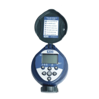
2. ABOUT THE 400A BATTERY OPERATED CONTROLLER
The 400A irrigation controller employs the latest irrigation programming features
to allow for complete control of any irrigation system. The 400A is available in
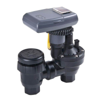
a single station model which includes a 3/4 in. anti-siphon valve, with a rain
sensor connection, and is powered by two AA batteries that can last up to 3
years [using name brand alkaline batteries]. The controller is enclosed in a
compact, waterproof housing to protect it from the elements.
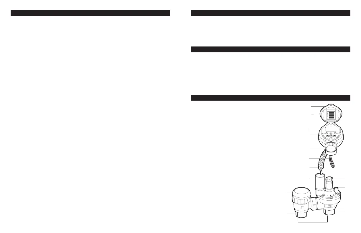
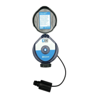
3. COMPONENT IDENTIFICATION
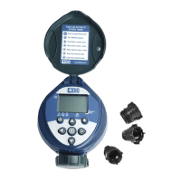
1. Controller cover
2. Quick reference label
3. LCD Display displays the icon-based
applications/ programs
4. 7 button programming keypad: Use
for programming, system on/off,
manual run and reviewing program
5. Battery compartment cap for
two AA alkaline batteries
(not included)
6. Rain sensor yellow wire connection
7. Collapsible 36 in. solenoid wire
8. DC solenoid
9. Anti-siphon air vent
10. 3/4 in. pipe thread outlet (FNPT)
11. Manual flow control
12. External bleed screw
13. 3/4 in. pipe thread inlet (FNPT)
14. Anti-siphon valve
w
e
r
y
q
u
i
s
t
d
o
a
g
f