23
SD12 - Getting Started
1-23
1.8 Routing Basics
1.8.1 Selecting Inputs & Outputs ...................................................
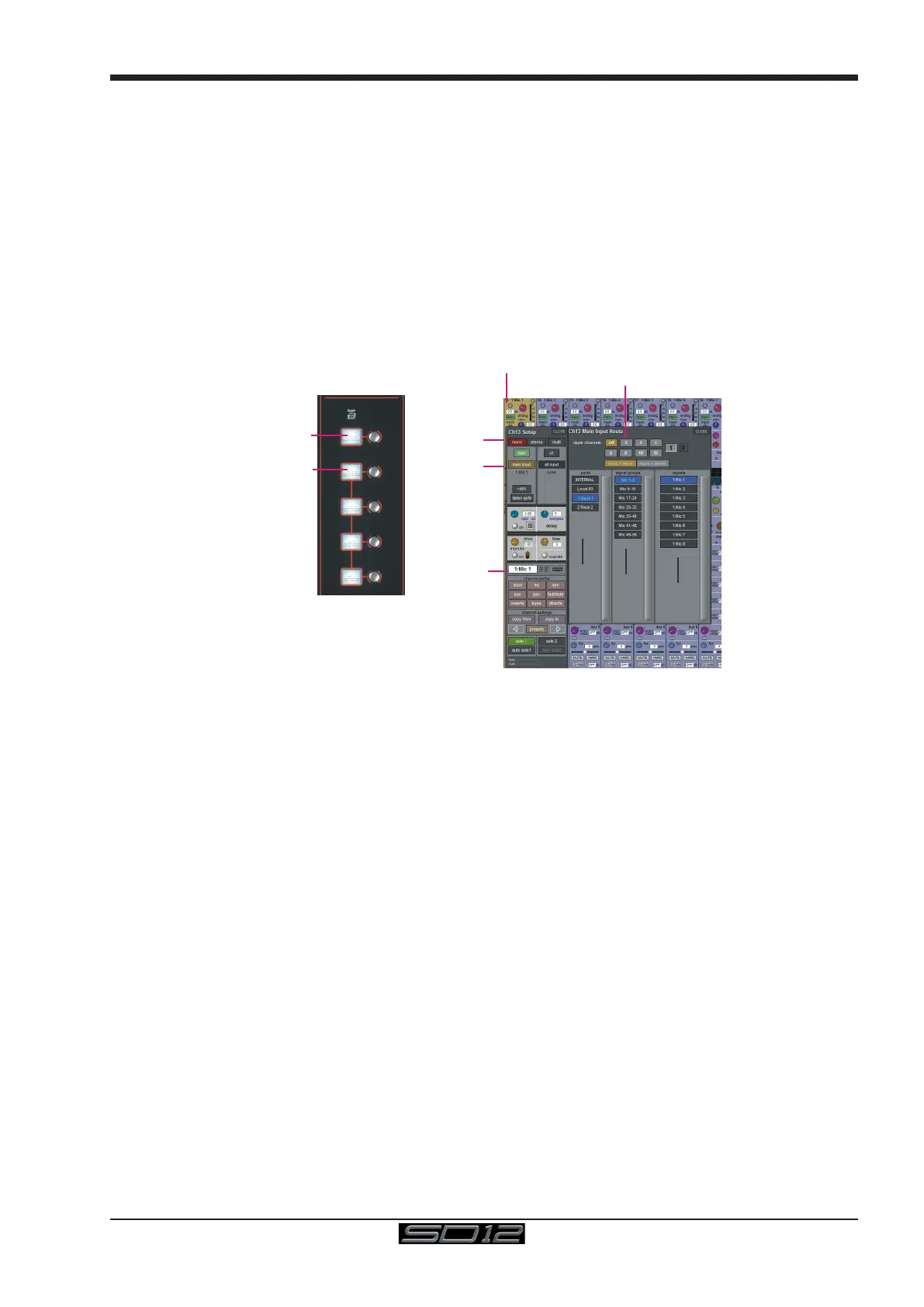
All channel input, output, insert send and insert return routing is done via routing displays, accessed via the dark grey routing buttons in
the channel Setup and Output displays (shown below for an Input channel’s input).
Note that multi-channel signals are routed individually, and then collected together as a "Multi Channel" as described
in the SD Software Reference Manual
To access Channel Input Setup, touch the top of an input channel display on the touchscreen.
To access Channel Output Setup, touch the bottom of any channel type's display on the touchscreen.
It is also possible to congure channel input and output routing directly from the Channel List display: Activate the Edit button at the
bottom of the display, then touch the input route box for a channel. A standard Setup display will then appear, from which a Routing
display can be opened. Inserts and Outputs can also be routed from this display by touching in the appropriate column.
Press Main Input
Label Channel
Select Format
Touch top of
Input Channel
Select or type
Number of Inputs
to Ripple Route
Select
Card
Select
Socket
Select
Rack
Select a Layer
Select a Bank
Within each display, there are three columns containing three levels of routing selection:
- The left-hand column contains the available ports within which the desired input or output might be located;
- The middle column, signal groups, then shows the available groups of inputs or outputs within that port;
- The right-hand column, signals, then displays the individual inputs or outputs available within that signal group.
The boxes in each column are lit blue to indicate that they are currently selected. If there is already a routing assigned within the display,
the port and signal group columns containing the current assignment will be half-lit.
Each output can only have one channel routed to it. The outputs that are currently in use by another channel display in blue text. If you
attempt to route a different channel to an output which is already in use, a conrmation box appears, indicating which channel is already
using it, and warning that continuing with the action will cause the old channel to be unrouted from this output. Press Yes to proceed, No
to cancel.
Note that when routing direct outs from Input channels or outputs from output channels, any number of available
signals can be selected. A new route selection will therefore be added to previous selections in these cases. However,
inputs, insert sends and insert returns can only route to/from one signal (in the case of mono channels) or two signals
(in the case of stereo channels). A new route selection will therefore result in the previous selection being lost for
inputs and insert sends and returns.
For stereo channels, left and right routes are presumed to be consecutive: When routing stereo signals, select the left route, and the
next signal in the list will be automatically selected as the right route. If the last signal in a signal group or port is selected as the left
route, the rst signal in the following signal group or port will selected as the right route.
For input and insert return routing, the INTERNAL port provides the following signal groups:
Misc: The oscillator, white and pink noise generators.
Graphic EQs: The outputs of the SD12’s internal graphic EQ’s.
Effects: The outputs of any effects sends that have been created
Channels: The direct outputs from the other input channels