Free in both directions Open Open
Controlled from left to right GND Open
Controlled right to left Open GND
Controlled on both sides GND GND
INFORMATION:
- ide pictogram 1 and 2 refer to the devices located on top of theS
equipment.
-The cables of the optical sensors (CN11) and the electromagnets
(CN10) are provided alongside Tx1500.
-The cable of the box sensor (CN9) is provided alongside the
collecting box kit (optional).
INFORMATION: PIC1 and PIC2 refer to the pictograms located on
each side of the equipment.
PIC1 (pin 15) PIC2 (pin 16) Pictogram 1 Pictogram 2
Open
Open
GND
GND
Open
GND
Open
GND
Red arrow
R
ed arrow
Red arrow
Red arrow
Green arrow
Green arrow
Green arrow
Green arrow
NO or NC Contact
Particularly about the CN11 connector, pins 13 and 14: Turnstile Tx1500 can be
configured
as follows to determine direction passage:
Pins 15 and 16, which control the side pictograms, must be configured
thusly:
The following sections concern important aspects of the control
board configuration
and connections of .Tx1500
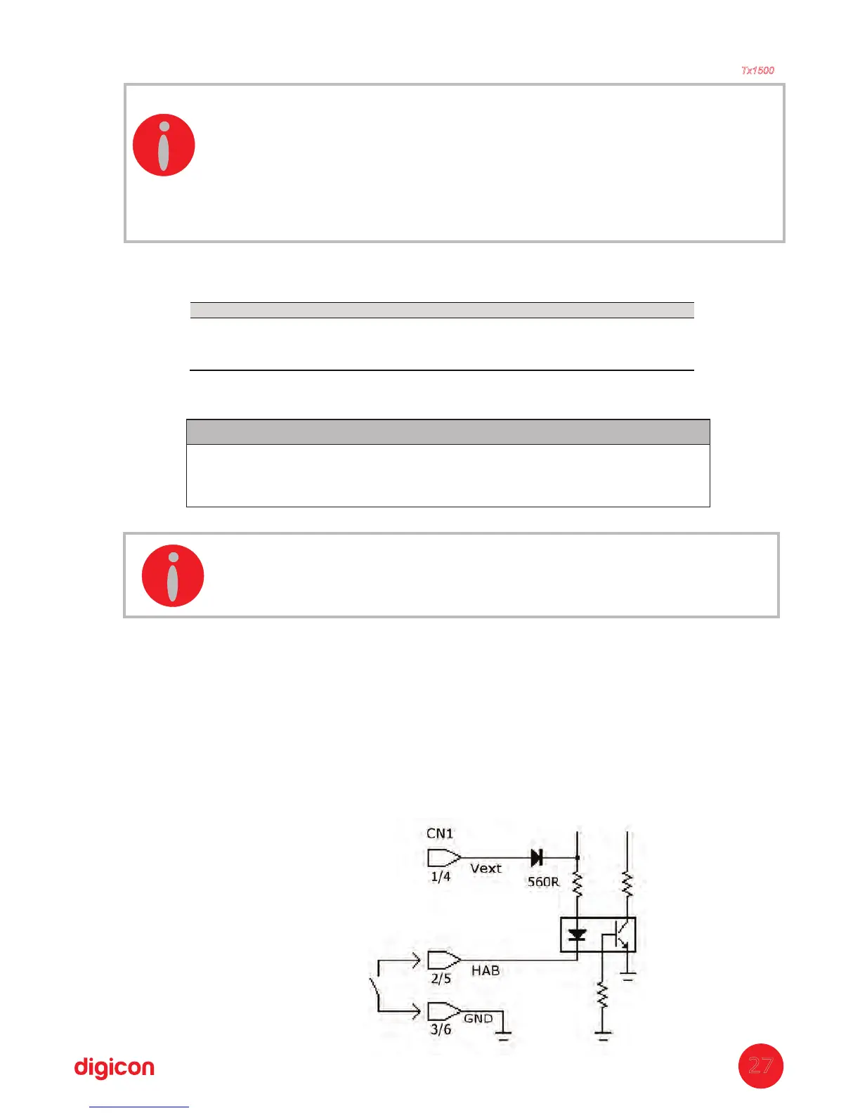
7.1 Inputs
The input signals or passage clearance (HAB1 and HAB2) can be originated by a relay
contact, pushbutton contact, tension from 5 to 24 V / c, from 110 to 220 V / c. Toac d ac d
enable passage t