1
DIN RELAY 4
Digital-Loggers.com
12
System Log & Notications
An internal system activity log is accessible from the Setup
page. The system log contains reports of all major activity
including login attempts, setting changes, relay state
changes, etc. Multiple relays and other DLI power controllers
can report to a centralized syslog server. Information on
setting that ups is at:
Digital-Loggers.com/Syslog.html
Email reports can be triggered by certain events.
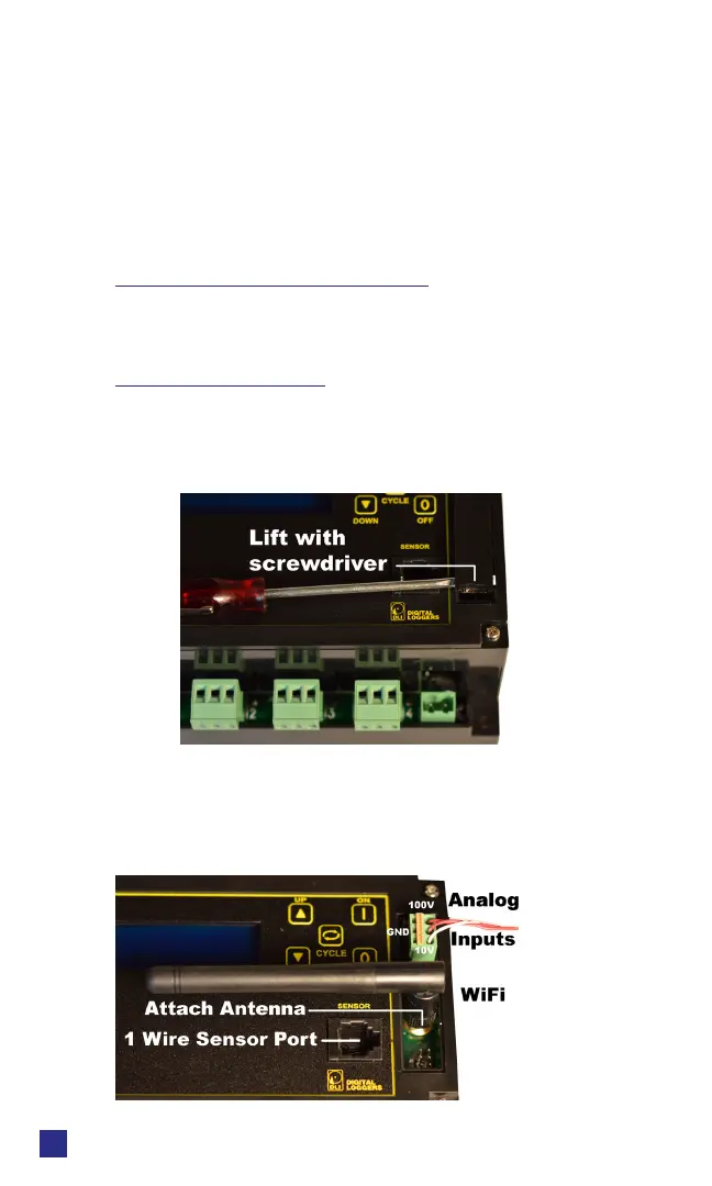
Accessory Hatch
The plastic hatch on the right side of the relay can be opened
to add a WiFi antenna or to connect analog inputs. Using
a small screwdriver, press gently on the lower edge of the
hatch. Push towards the buttons The hatch will ex and pop
open.
The antenna and/or ADC connector may be attached when
the hatch is removed. A three pin connector is provided for
ADC input. The upper pin is scaled for 0-100VDC, and the
lower pin is 0-10VDC. The center pin is a ground reference
bonded to the negative power input.
 Loading...