© 2020 Digitrax, Inc. www.digitrax.com
26
26
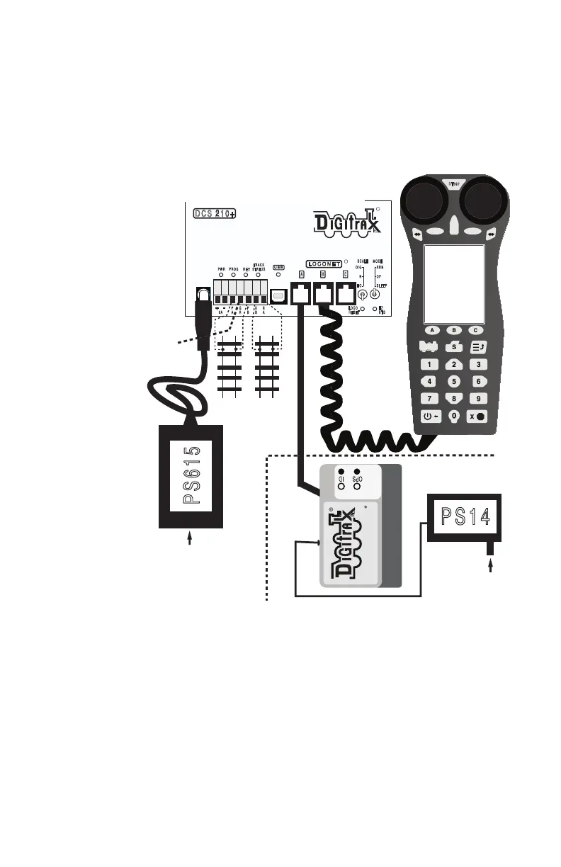
9.0 Evolution Express setup
The DCS210+ is the command station and track booster part of an Evolution
Express control system. To setup a minimal system, to confirm functionality:
1. Connect the DCS210+ to the AC-powered PS615 DC power supply using
the 2mm DC jack, and switch settings, as shown in gure 3 below. The
DCS210+ will beep and the PWR led will light up. The PS615 is a uni-
versal DC supply and operates off 85 to 240Volts AC, 50/60Hz.
2. Connect a DT602/D throttle via a LocoNet RJ12 cable to any one of the
three LocoNet jacks A/B/C on DCS210+.
3. The DT602 will power up its LCD screen, and log on to the DCS210+.
You will now be able to follow earlier section 2.0 Quick Start Guide steps.
4. The layout tracks and/or programming track may be connected and pow-
ered up to run or program decoded locomotives.
5. For the Duplex version: Connect and power up the UR93 Duplex trans-
ceiver and its PS14 supply as shown in the dashed section of gure 3.
Install 3 AA batteries and then plug in a DT602D/DE [or other duplex
compatible throttle] into a LocoNet RJ12 jack. The throttle will automati-
cally discover the UR93 current Duplex RF system NetName and Channel
number settings.
E Z
RTS
DCS 210+
R
L O C O N E T
A B
R
C
PWR PROG N E T
TRA CK
STA TUS
M ODE
RUN
O P
S LE E P
SCALE
O/G
N
H O
+
P
A
G
R
P
B
R
B
R
A
5 A
L OCO
R ESET
-
8 A
UR93
Complete Train Control
PS615
PS1 4
85-240V A C
85-240V A C
DT60 2
E
D F
Duplex Version addition
Program
Track
Mainline
Tracks
IEC Cordset
Booster
Ground to
other boosters
Figure 3: Evolution Express connections: