9
7.2 Din rail installation:
The first step is to check the grounding and
stability of the guide rail: the guide rail slot of the
switch is clamped into the guide rail; The second
step: from the center to both sides of the guide
rail positioning screws in order. Step 3: Use
screws to fix the mounting rail card slot on the
fixed guide groove at both ends of the guide rail
to ensure that the guide rail and the switch are
fixed on the guide rail vertically and stably.
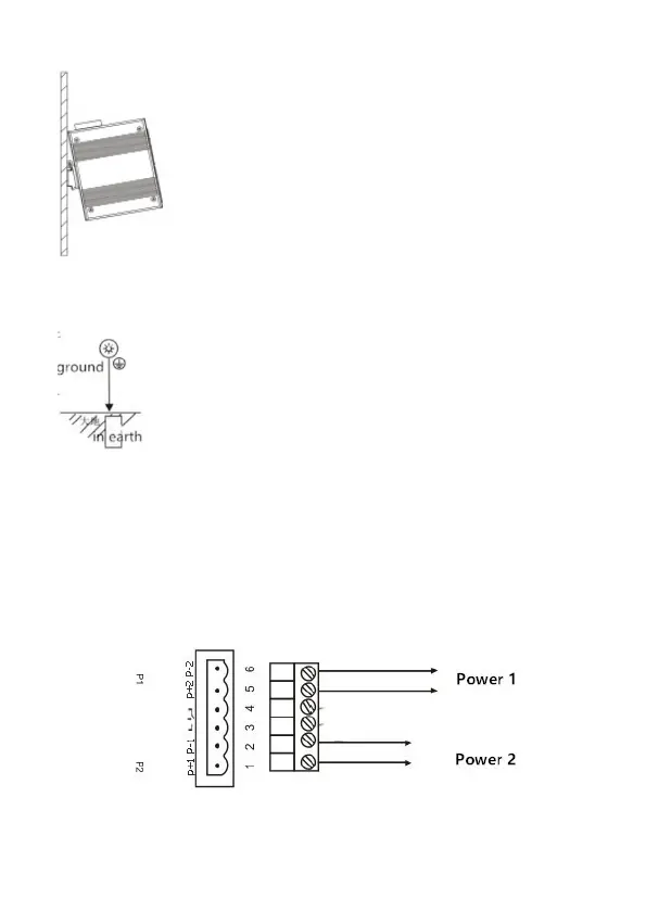
7.3 grounding
Fix the grounding wire to the grounding screw
above the switch, and ensure good reliable
connection of the grounding system.
7.4 Power Connection
Insert the power cord into the specified position of the 6-core terminal,
and insert the terminal into the standard power supply inlet (P+1 and
P-1 input corresponding to the first power supply P1, and P+2 and P-2
input corresponding to the second power supply P2). The available
voltage standard of the power supply is supported from 12VDC to
52VDC