Do you have a question about the Digitus DN-651160 and is the answer not in the manual?
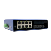
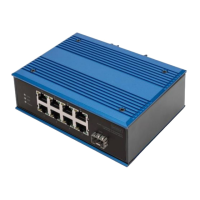
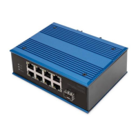
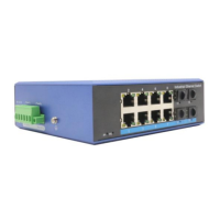
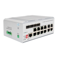
This document provides a Quick Installation Guide for the DIGITUS Industrial 8 + 4-port L3 managed Gigabit Ethernet (PoE) Switch, models DN-651160 and DN-651161.
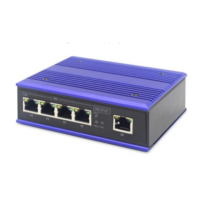
This is an L3 managed industrial PoE Ethernet switch designed for robust and reliable network solutions in harsh industrial environments. It features 8 ports of 10/100/1000Mbps RJ45 (with PoE capability for model DN-651161) and 4 ports of 1000/2500/10000Mbps SFP, along with a console port for management. The switch is built to ensure communication network stability by adopting Layer 2 protocols essential for industrial sites. Its design emphasizes low power consumption and a fanless operation, eliminating noise interference. The device is engineered to withstand extreme temperatures ranging from -40°C to 80°C and boasts strong EMC electromagnetic compatibility, ensuring stable performance in challenging industrial settings. It is ideal for applications such as factory automation, intelligent transportation, and video surveillance, providing a secure and dependable network terminal access.
The switch offers a comprehensive set of features for data control, redundant networking, multicast management, redundancy backup, VLAN support, link aggregation, Quality of Service (QoS), security management, and monitoring.
It supports 802.3X full-duplex flow control, which helps prevent packet loss in congested networks by pausing data transmission when the receiving buffer is full. Additionally, it includes network storm suppression to prevent broadcast, multicast, or unknown unicast storms from overwhelming the network, thereby maintaining network stability.
For enhanced network reliability, the switch supports multiple redundancy protocols. These include Spanning Tree Protocol (STP), Rapid Spanning Tree Protocol (RSTP), and Multiple Spanning Tree Protocol (MSTP), which prevent network loops and provide path redundancy. It also supports Ethernet Ring Protection Switching (ERPS), offering a self-healing time of less than 20ms, ensuring rapid recovery from link failures in ring topologies.
The device supports IGMP Snooping V1/V2/V3, which optimizes multicast traffic by forwarding it only to ports where multicast receivers are present, rather than flooding it across the entire network. This conserves bandwidth and improves network efficiency.
To further enhance reliability, the switch supports the Virtual Router Redundancy Protocol (VRRP). VRRP allows multiple routers on a multi-access link to share a single virtual IP address and MAC address, providing automatic failover if the primary router becomes unavailable.
The switch supports IEEE 802.1Q VLANs, enabling the logical segmentation of networks. This effectively isolates broadcast domains, improving network security and performance by confining traffic within specific VLANs.
It supports both static and dynamic link aggregation (IEEE 802.3ad). This feature allows multiple physical links to be combined into a single logical link, increasing bandwidth and providing link redundancy. This ensures perfect bandwidth utilization and improved network resilience.
The switch offers robust QoS capabilities, supporting Class of Service (CoS) and Differentiated Services Code Point (DSCP) for traffic prioritization. It provides 4 queues and supports Weighted Round Robin (WRR) and Strict Priority (SP) scheduling modes, allowing administrators to prioritize critical traffic and ensure optimal performance for latency-sensitive applications.
Security is a key aspect, with support for Access Control Lists (ACLs) to filter network traffic based on various criteria, enhancing network security. It also supports 802.1X port-based network access control, which authenticates devices connecting to the network, preventing unauthorized access.
The switch can be managed through various methods, including a web-based graphical user interface (WEB), Command Line Interface (CLI), and Simple Network Management Protocol (SNMP). These options provide flexibility for network administrators to configure and monitor the device.
For effective network monitoring and maintenance, the switch supports port mirroring, allowing traffic from one port to be duplicated to another for analysis. It also provides interface status monitoring and log management, which helps in troubleshooting and auditing network events.
The device supports static routes for simplified network configuration and IPV6 for future-proof networking. It also supports NTP clients for time synchronization and Precision Time Protocol (PTP) (1588v2) for highly accurate time synchronization, crucial for industrial control systems.
The switch includes a serial port-based management system program debugging port, located on the front panel. This allows for command-line login and detailed configuration and troubleshooting. The console port operates at a baud rate of 115200.
The front panel features various LED indicators to provide real-time status information:
To prevent damage to the equipment and personal injury, several precautions must be followed during installation:
The installation process for a DIN rail involves three steps:
A grounding wire should be fixed to the grounding screw located above the switch. This ensures a good and reliable connection to the grounding system, which is essential for safety and electromagnetic compatibility.
The power cord is inserted into the specified position of the 6-core terminal. This terminal is then inserted into the standard power supply inlet. For the first power supply (P1), P+1 and P-1 inputs are used. For the second power supply (P2), P+2 and P-2 inputs are used. This setup supports two-way power redundancy backup, enhancing reliability. The device also includes built-in overcurrent protection (4.0A) and reverse connection protection.
The management system can be accessed via a console port or a web interface.
The device is classified as a Class A product. In a home environment, it may cause radio interference, and users might need to take appropriate measures. Assmann Electronic GmbH declares that the Declaration of Conformity is part of the shipping content, and if missing, it can be requested by post from their manufacturer address.
| Switch type | Unmanaged |
|---|---|
| Basic switching RJ-45 Ethernet ports type | Gigabit Ethernet (10/100/1000) |
| Port type | RJ-45 |
| Switching Capacity | 16 Gbit/s |
| MAC Address Table | 4000 entries |
| Jumbo Frames Support | Yes |
| Jumbo frames | Yes |
| Packet buffer memory | 128 KB |
| Store-and-forward | Yes |
| Housing material | Metal |
| Power supply included | Yes |
| Power Supply | External |
| Weight | 430 g |