4
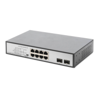
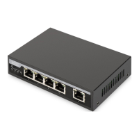
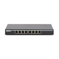
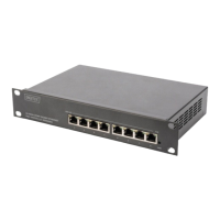
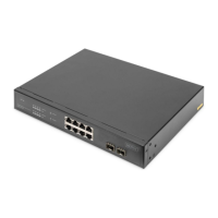
Front Panel (left)
The Front Panel Consists of Ethernet Ports.
The LED indicators are also located on the panel.
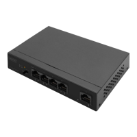
DIP Switch: Control port 1-2 in different power supply modes
Note: After change the mode, there is no need to restart manually to make the
corresponding configuration take effect.
LED Indicator
Off: No Power supply.
Light: Indicates the switch has power.
Off: No device is connected to the corresponding port.
Light: Indicates the link through that port is successfully
established at 10/100/1000Mbps.
Blink: Indicates that the Switch is actively sending or receiving
Off: No PoE powered device (PD) connected.
Light: There is a PoE PD connected to the port, which supply
power successfully.
Blink: Indicates port abnormal power supply.
Rear Panel (right)
The rear panel of the PoE Switch indicates an AC inlet power socket, which accepts
input power from 100 to 240V AC, 50/60HZ.
Power socket
Connect the female connector of the power cord here, and the male connector to
the AC (Alternating Current) power outlet. Please make sure the voltage of the
power supply meets the requirement of the input voltage.
Grounding column
The switch already comes with lightning protection mechanism. You can also ground
the switch through the PE (Protecting Earth) cable of AC cord or with Ground Cable.