4
5. Hardware Description
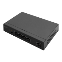
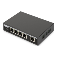
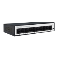
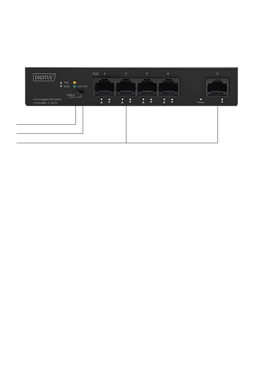
Front Panel
The front panel consists of 5*10/100/1000Mbps adaptive RJ45 ports and
related indicators, as shown in the following figure:
LED Indicator
DIP Switch
5*10/100/1000 Mbps RJ45 Ports
4-Port Gigabit+1GE Port description:
10/100/1000Mbps RJ45 Ports
Supports 10Mbps, 100Mbps and 1000Mbps rate adaptation, and supports
auto-MDI /MDIX. 1-4 ports support PoE power supply. PoE ports
automatically detect PD devices and supply power to PD devices that
comply with IEEE 802.3af/at standards. Each port has a maximum of 30W.
Each port has a corresponding indicator, that is, the indicators 1-5 on the
panel in the figure above.
DIP Switch
The DIP switch located on the left panel.
Default mode: when CCTV closed the factory default mode can normal
communication between port 1~5
CCTV mode: 1-4 port can be isolated each other but 1-4 port can connect
to 5-port after open CCTV to stop broadcast storm to increase forwarding
rate of frame. The CCTV mode, up to 250m PoE distance allows you to
expand you network via Ethernet cable to where there is no power line or
outlet but where you want to fix device such as IP Cameras.
Note: after changing the mode, there is no need to restart manually.
 Loading...