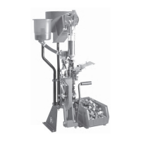
Be sure to secure the small, but important, screw
located at the rear of the bowl at the base. This little
screw (#13685) secures the entire bowl assembly to
the casefeed post (17123).
Fig. 8
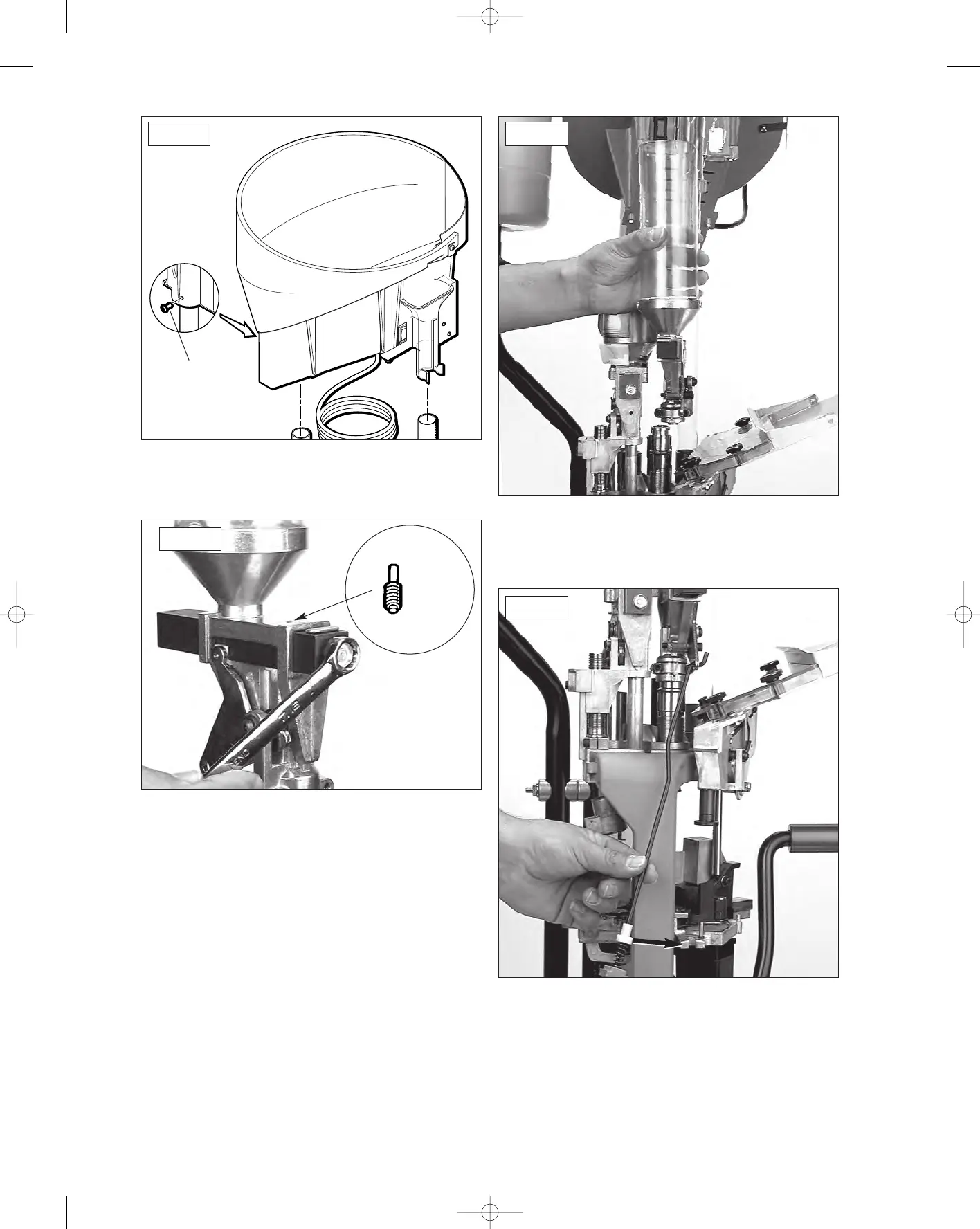
7. The powder measure (#17817) is the next item
we’ll be installing on the machine. Familiarize
yourself with its operation – every complete stroke of
the powder bar dispenses one charge of powder. The
dispenser is hull activated.
Using a 7/16” wrench, rotate the bolt located on
the end of the powder bar – counterclockwise will
reduce the powder charge weight, clockwise will
increase the powder charge weight.
Fig. 9
Be sure to install the powder measure plug
(#13921) here – see arrow
Fig. 9.
8. Remove the blue cap on the powder die
(#16744). Loosen the two Allen screws and place the
powder measure (#17817) on the powder die
(#16744). The clamp must lock into the groove of the
die, then secure the two Allen screws firmly.
Fig. 10
9. Locate the parts bag for your machine. Enclosed
is a powder bar return rod (#17350)
Fig. 11. The
powder bar return rod (#17350) must be inserted into
the bellcrank from its left side. On the bottom of the
rod is a blue wing nut (#13799), spring and white rod
bushing (#18086). Slide this end into the receiver (
see
19
13685
Fig. 8
Fig. 9
Fig. 10
Fig. 11
#13921