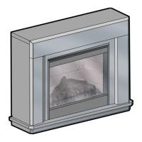
Electronic Economiser Temperature Control
This sensitive output control 3 will switch the radiant heater
elements ON and OFF to accurately maintain the level of
comfort that you have selected. Select low or high heat -
then turn the control dail to 7, when the room reaches a
comfortable level of warmth, turn the dial down until the
electronic controlled elements turn off. The control dial
should be left at this setting, the electronic control will the
switch the element ON and OFF as needed to maintain your
chosen level.
Maintenance
WARNING : ALWAYS DISCONNECT FROM THE POWER
SUPPLY BEFORE ATTEMPTING ANY MAINTENANCE.
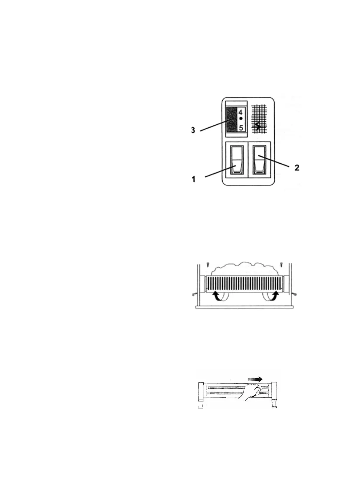
Removing the guard
Unscrew the 2 screws at each end of the guard, then withdraw
the lower edge of the guard rst. - see Fig. 3
Replace the guard in reverse order.
Removing the elements
The element holders are spring loaded. To remove an element,
grip one end using a soft cloth to protect the surface, then push
carefully but rmly to one side until the other end disengages
from its socket. Withdraw the element carefully - see Fig. 4.
Ret in reverse order.
Cleaning the reector
The reector may be more easily cleaned if the elements are
rst removed (see previous). Wipe the reector with a warm
soapy cloth, then buff with a soft dry cloth.
DO NOT use abrasive cleaning powders or metal polish.
Fig. 4
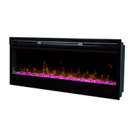
Introduction
Unpack the heater carefully and retain all packaging for
future use.Always ensure that the heater is stood on a rm,
level base near to, but not directly beneath, a suitable mains
supply socket.
This fuel effect heater is to be a wall mounted product, either
at raised or oor level.
Electrical connection
WARNING – THIS APPLIANCE MUST BE EARTHED
This heater must be used on an AC ~ supply only and the
voltage marked on the heater must correspond to the supply
voltage.
Before switching on, please read the safety warnings and
operating instructions.
In the event of replacing the fuse in the plug supplied, a 13 amp
fuse approved by ASTA to BS1362 must be used.
Using the heater
Before switching on remove the fuel effect (two screws - see
Fig. 3) and check that the lamp and icker rotor are positioned
correctly.
The icker rotor should sit horizontal on its pin and spin freely
without fouling its mounting brackets. If necessary, adjust the
bracket by bending slightly.
Ret the fuel effect by inserting the front edge rst, then secure
with the screws. Ensure that all packing items are removed
(read any warning labels carefully) and that the radiant
elements and fuel effect are positioned correctly, otherwise
damage may occur.
Operation
When you are certain that you have completed the installation,
plug in and switch on at the wall socket.
The fuel effect will light up as soon as the plug is plugged in
and the socket turned on, even if the heat selector switches
are in the OFF position.
The icker rotor will begin to rotate after a minute or so.
The lamps will go out when the power is turned off at the socket
or the product is unplugged.
Radiant Elements
You have a choice of low heat (two elements 1332W) or high
heat (three elements 1998W). Both settings have electronic
temperture control - see below. A switch is set to ON when the
red section is visible on the switch.
Low Heat Setting - see Fig. 2
Press switch 1 to ON. Two elements will glow and, when the
temperature selected on the electronic control dial 3 is reached,
one of the elements will turn off, it will come back on when the
temperature falls.
High Heat Setting
Set switches 1 & 2 to ON. All three elements will glow and,
when the temperature selected on the electronic control dial 3
is reached, two of the elements will turn off, it will come back
on when the temperature falls.
The unit can be returned to Low Heat by pressing switch 2
to OFF.
Fig. 3
Fig. 2
 Loading...