Using the Heater
Plug in and switch on at the wall socket.
The clock will operate all the time that the heater is connected to the
mains supply, regardless of the setting of the control unit.
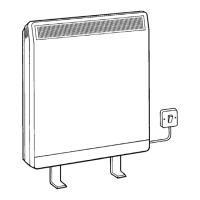
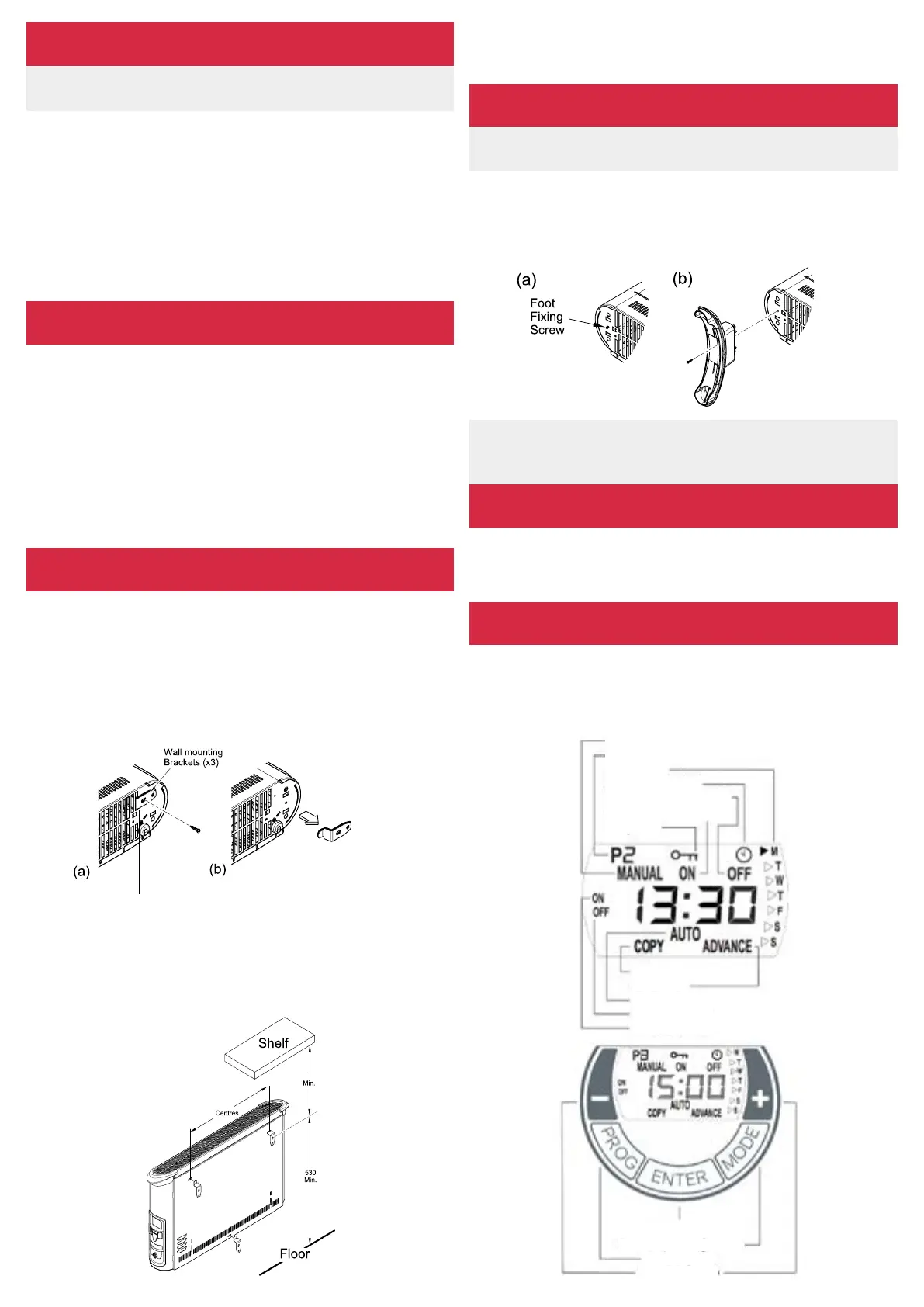
Lay the heater on its back and remove the wall mounting brackets - see
‘Wall Mounting’. Locate the footxing screw (see ‘a’ in Fig. 3) and remove
the screw using an X-head screwdriver, then align foot over slots and
holes in base (see ‘b’ in Fig. 3) and push into the slots. Finally take the
foot xing screw, insert and tighten using a screwdriver to secure the foot.
Locate the heater on the top brackets and allow it to hang in place. Fit
the bottom bracket into the slot in the heater and then x it to the wall.
Test that the heater is now securely xed to the wall.
Free Standing Use
WARNING: NEVER USE THE HEATER FREE STANDING WITHOUT
THE FEET FITTED
NOTE: The wall mounting brackets must be removed before the
foot can be tted. The brackets should be retained for wall
mounting the product in the future if required
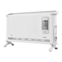
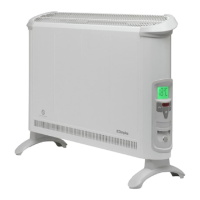
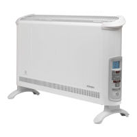
Control Unit
The heater is supplied with a congurable electronic control, consisting
of a display, a LED screen and ve membrane buttons. The control unit
is located on the right hand side of the panel.
The set functions and values are shown on the display.
The LED lights up red when heating ON
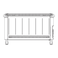
Wall Mounting
Three idential wall mounting brackets are secured to the base of the
heater with axing screw. To wall mount the appliance, rst removve
the brackets as follows:
Lay the heater on its back.
Following the sequence in Fig. 1 - identify and remove the xing screw
securing the brackets located beside the mains cable as shown in (a),
then pull out the brackets and rotate them to disengage them from the
slot. Withdraw the brackets from slot (b).
Select a suitable position on a wall, near to a mains power socket, making
sure that there is
at least
230mm below the heater at
least
450mm above
the heater of unobstructed space. See also ‘Positioning the hetaer’. Fix
the two top retaining brackets to the wall, using suitable xings, 3kW
models at 478mm centres - see Fig. 2.
(b)
Fig. 1Wall Mounting Brackets
Positioning the Heater
WARNING: DO NOT USE THE HEATER UNTIL THE FEET OR WALL
BRACKETS ARE FITTED CORRECTLY
The product can be used as an installed or portable unit. Once the desired
application has been decided upon and the requirements below have
been met, the product is ready to be used. Simply plug in and switch
on at the wall socket.
There are various control options available with various combinations via
the membrane buttons and segmented display. Please note - the element
has been coated with a protective lm which will burn o during the
rst few minutes of use and may cause a small amount of fuming. This
is quite normal - the fumes are non-toxic and will quickly disappear. We
recommend that you open a window to ventilate the room when using
the heater for the rst time.
Using the Heater
Always ensure that the heater is stood on a rm, level base near to, but
not directly underneath a suitable mains supply socket.
Ensure that curtains and furniture are not positioned close to the chosen
position, as this would create a potential re hazard.
We recommend that the heater should be wall-mounted in rooms where
children may be left unattended, see ‘Important Safety Advice’.
If young children, the aged or inrm are likely to be left in the vicinity of
the heater, we advice that the adequate precautions should be taken.
We recommend that a guard be tted to ensure contact with the heater
is avoided and objects canot be inserted into the product.
For further information, please contact our guard supplier direct on Tel.
No. 0207 987 1184, or in case of diculty or for further advice contact
the Customer Helpline.
(a)
Fig. 3
Fig. 2
Value down/up
Set program
Select Operating Mode
Save Entry
Copy
Advance
Automatic Operation
Time block o
Time block on
Manual Operation
Program no. (1-4)
Weekday
Setting the time
Heating operation o
Heating operation on
Key lock
 Loading...