E-8
English
7
Heat pump operation can be blocked as required if domestic hot
water is to be prepared using a second heat generator. This is
achieved by removing the factory-mounted copper bridge A2 (at
terminal strip X5, see Section 5.3) and integrating a floating con-
tact from the second heat generator regulation in the same posi-
tion. An external regulation must not lead to the maximum
switching frequency (12 operations/h) of the heat pump being ex-
ceeded. It may be necessary to take the local utility company
(EVU) specifications into consideration in this regard.
Relay for heat exchanger operation
Relay with a floating contact (hot-water heat pumps with internal
heat exchanger only) to control the ancillary devices (pump, so-
lenoid valve etc.) for operation with a second heat generator. The
relay contact is closed when the "Heat Exchanger" switch is acti-
vated and a hot water request from the hot-water heat pump tem-
perature controller is present.
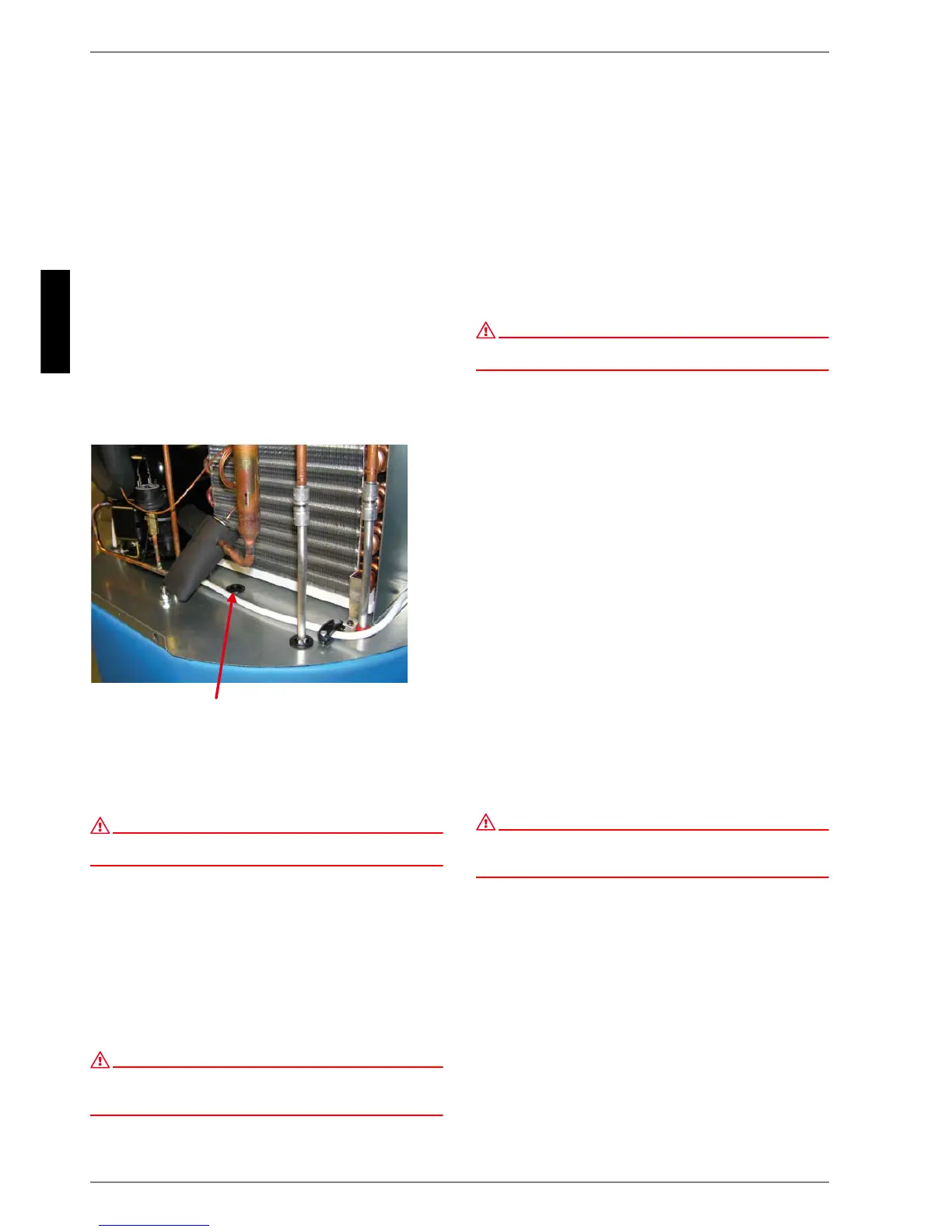
Sensor pipe for external temperature sensors
A vertical sensor pipe ∅
i
12mm (opening in the bottom plate
sealed with a leading-in tube) for an external heat sensor is fitted
in the rear of the hot-water heat pump and a cable feedthrough is
available in the rear panel.
External temperature sensor installation position
(device cover removed)
7 Maintenance
ATTENTION!
Disconnect the power supply before opening the hot-water heat pump;
observe possible coasting of ventilator.
General information
The hot water heat pump is virtually maintenance-free. A one-off
visual inspection for possible leakage in the water system or
stopping-up of the condensate outflow should take place a few
days after the maintenance work has been carried out.
Do not carry out any maintenance work on the refrigerating cir-
cuit of the heat pump.
Only use a damp cloth and soap solution for cleaning the hot-
water heat pump.
ATTENTION!
Ensure water does not come into contact with the operator controls.
Unplug mains plug/disconnect the power supply before beginning any
cleaning work.
7.1 Water Circuit / Condensate
Outflow
The water circuit check is limited to filters that may have been in-
stalled on-site, and possible leakage. Dirty water filters should be
cleaned and replaced if necessary. Occasionally check the seal
valve in the condensed water hose for contamination; replace if
necessary.
7.2 Air Circuit
Maintenance work is limited to cleaning the evaporator on a reg-
ular basis, and as needed.
ATTENTION!
Risk of injury caused by sharp-edged fins. Fins must not be deformed or
damaged!
If air filters are used, they should be regularly checked for con-
tamination and cleaned and replaced if necessary.
7.3 Corrosion Protection Anode
The corrosion protection anode installed in the hot water cylinder
should be electrically checked on a regular basis, at least every
two years after start-up, and be replaced if necessary. Electrical
checking is carried out by means of a suitable ammeter, without
draining the tank.
Procedure:
1) Unplug PE cable from protection anode tab.
2) Connect ammeter (0...50mA) between PE cable and tab.
3) Evaluation of protection anode wear:
Measured value > 1 mA ⇒ protection anode is in working
order.
Measured value < 1 mA ⇒ protection anode must be tested
or replaced.
If electrical testing does not provide any clear results, a visual in-
spection of the protection anode by a technician is recom-
mended.
Should replacement of the protection anode [by a technician] be
necessary, the tank must be drained via the valve provided (fitted
during installation - see Appendix).
ATTENTION!
Malfunctioning protection anodes reduce the operating life of the device!
(Reactive anode: electrically insulated magnesium anode with selenium
according to DIN 4753 Part 6)