3 4
PART DIAGRAMS
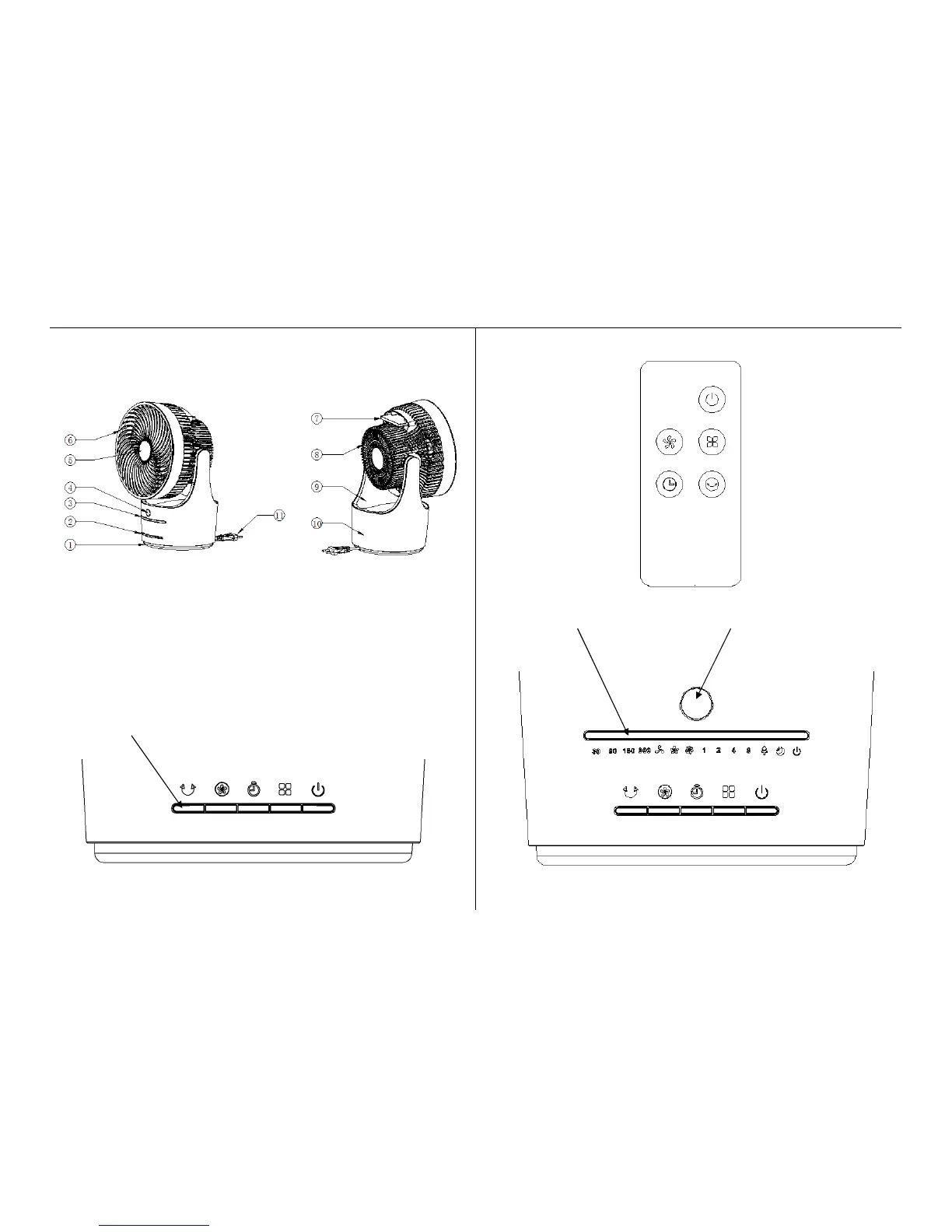
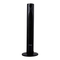
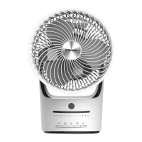
Product structure
1. Base 2. Control Buttons 3. LED indicator lights
4. IR Receiving window 5. Decorative Cover 6. Fan guard
7. Remote Controller 8. Rear housing 9. Vertical Oscillation Support
10. Fan Body 11. Power cord
Control Button panel
(See Operating Instructions section for details of symbols)
Remote Control
LED indicator light display panel & IR remote signal receiving window