Work must only be carried out by qualified personnel. Before carrying out
any work, always ensure that there is no voltage present at the terminals.
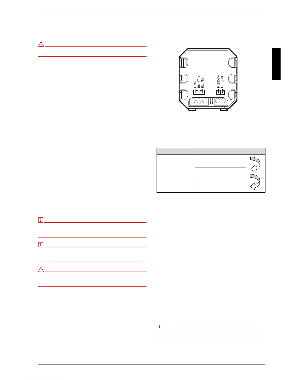
4.4.1 Power supply
The power supply is connected to terminals L and N (1~ /N,
230 V, 50 Hz) of the device via a 2-core cable (to be provided by
the customer). Cable cross sections of 0.5 mm² and 1.5 mm² are
permissible. (see Fig. 4.7:)
Fig. 4.7:
4.4.2 Bus connection to the heat pump manager
A bus connection must be established on site between the heat
pump manager and the Smart-RTC. This requires a shielded 2x
0.25 mm² cable with a maximum length of 50m. The cable
screening is used as the GND connection.
The following terminals (see Table 4.1:) must be connected:
Table 4.1:
4.5 Start-up
If communication cannot be established, the address set on the Smart-
RTC must be checked. WPM software version L03 requires Address 1;
from version L04 Address 50 must be set on the Smart-RTC.
Press the "Rapid heating" and "Key lock" buttons simultaneously
for approximately 3 seconds to check the address. "Code" is
displayed. Turn the rotary pushbutton to change the value and
press the button to confirm the new value. First the value "22"
must be selected and confirmed. Following this, the required
address must be set and confirmed using the rotary pushbutton
on the screen displaying "Addr". Finally, use the rotary
pushbutton to select the screen displaying "ESC" and confirm to
leave the menu.
The Smart-RTC function must be activated on the heat pump
manager. In the menu for technicians, the regulation must be set
to room temperature (Settings - Heating circuit 1 - Room
temperature regulation) and the temperature sensor must then
be set to Smart-RTC (Settings - Heating circuit 1 - Temperature
sensor).
The greater the deviation between the actual room temperature
and the room set temperature, the faster the return set
temperature is adjusted. The response time can be changed by
means of the adjustable interval value (I value) if required. The
longer the response time, the slower the room set temperature is
adjusted.
Prerequisites:
Deactivation of individual room control, if present, in the
reference room (e.g. room regulation with control via control
valve)
Entry of a minimum return set temperature to prevent the
building from cooling down if there is internal heat recovery
in the reference room.
Entry of a maximum return set temperature to prevent the
building from overheating (e.g. if the windows are open)
Constant room set temperature with the elimination of as
many raising and lowering operations as possible
 Loading...